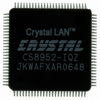
CS8952-IQZ Cirrus Logic Inc, CS8952-IQZ Datasheet - Page 58

CS8952-IQZ
Manufacturer Part Number
CS8952-IQZ
Description
IC TXRX 100/10 PHY 100TQFP
Manufacturer
Cirrus Logic Inc
Type
Transceiverr
Datasheet
1.CS8952-IQZ.pdf
(81 pages)
Specifications of CS8952-IQZ
Package / Case
100-TQFP, 100-VQFP
Protocol
MII
Voltage - Supply
4.75 V ~ 5.25 V
Mounting Type
Surface Mount
Minimum Operating Temperature
0 C
Mounting Style
SMD/SMT
Product
Ethernet Transceivers
Number Of Transceivers
1
Standard Supported
100BASE-FX or 100BASE-TX or 10BASE-T
Data Rate
10 Mbps or 100 Mbps
Supply Voltage (max)
6 V
Supply Voltage (min)
- 0.3 V
Supply Current (max)
+/- 10 mA
Maximum Operating Temperature
+ 70 C
Lead Free Status / RoHS Status
Lead free / RoHS Compliant
Number Of Drivers/receivers
-
Lead Free Status / Rohs Status
Lead free / RoHS Compliant
Other names
598-1208
Available stocks
Company
Part Number
Manufacturer
Quantity
Price
Company:
Part Number:
CS8952-IQZ
Manufacturer:
CIRRUS
Quantity:
560
Company:
Part Number:
CS8952-IQZ
Manufacturer:
CIRRUS
Quantity:
70
Part Number:
CS8952-IQZ
Manufacturer:
CRYSTAL
Quantity:
20 000
Company:
Part Number:
CS8952-IQZR
Manufacturer:
Cirrus Logic Inc
Quantity:
10 000
6.18
CrystalLAN™ 100BASE-X and 10BASE-T Transceiver
DS206F1
15
14
13
12
11
10
9
8
7
6
BIT
Full Duplex
Link OK
15
7
Link OK
Power Down
Receiving Data
Descrambler Lock
Disable CRS on
Time-out
Auto-Neg Enable
Status
PAUSE
FEFI Enable
Full Duplex
10BASE-T Mode
Self Status Register - Address 19h
NAME
10BASE-T
Power
Down
Mode
14
6
Read Only 0
Read Only 1
Read Only 0
Read Only 0
Read/Write Reset to the logic
Read Only If auto-negotiation
Read Only 0
Read/Write 0
Read Only If a full duplex
Read Only 0
CIM Status
Receiving
TYPE
Data
13
5
inverse of the
value on the
REPEATER pin.
is enabled via the
AN[1:0] pins, reset
to 1; otherwise,
reset to 0.
mode is enabled
via the AN[1:0]
pins, reset to 1;
otherwise, reset to
0.
Descrambler
RESET
Lock
12
4
Disable CRS
on Time-out
When set, this bit indicates that a valid link connec-
tion has been detected. The type of link established
may be determined from bits 6, 7, and 9. When clear,
this bit indicates that a valid link connection does not
exist. This bit may be used to determine the current
status of the link.
When high, this bit indicates that the CS8952 is in a
low power state.
This bit is high whenever the CS8952 is receiving
valid data. It is a direct copy of the state of the
RX_DV pin accessible by software.
When high, this bit indicates that the descrambler
has successfully locked to the scrambler seed of the
far-end transmitter and is able to descramble
received data.
This bit controls the state of the CRS pin upon a
descrambler time-out. When set, CRS will be forced
low upon a descrambler time-out, and will not be
released until the descrambler has re-acquired syn-
chronization.
This bit reflects the value of bit 12 in the Basic Mode
Control Register (address 00h). When set, it indi-
cates that auto-negotiation has been enabled. When
clear, this bit indicates that the mode of the CS8952
has been forced to that indicated by bits 6, and 7.
When set, this bit indicates that the Flow-Control
PAUSE function has been negotiated. This indicates
that both the local device and the link partner have
advertised this capability.
This bit controls the Far-End Fault Generate and
Detect state machines. When this bit is set and auto-
negotiation is disabled (bit 10 is clear), both state
machines are enabled. When clear, this bit disables
both state machines.
When set, this bit indicates that the CS8952 has
been configured for Full-Duplex operation.
When set, this bit indicates that the CS8952 has
been configured for 10 Mb/s operation.
11
3
Enable Status
PHY Address
Auto-Neg
10
2
DESCRIPTION
PAUSE
9
1
CS8952
FEFI Enable
8
0
58


