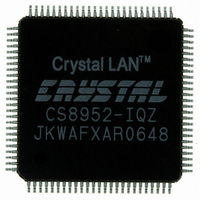
CS8952-IQZ Cirrus Logic Inc, CS8952-IQZ Datasheet - Page 68

CS8952-IQZ
Manufacturer Part Number
CS8952-IQZ
Description
IC TXRX 100/10 PHY 100TQFP
Manufacturer
Cirrus Logic Inc
Type
Transceiverr
Datasheet
1.CS8952-IQZ.pdf
(81 pages)
Specifications of CS8952-IQZ
Package / Case
100-TQFP, 100-VQFP
Protocol
MII
Voltage - Supply
4.75 V ~ 5.25 V
Mounting Type
Surface Mount
Minimum Operating Temperature
0 C
Mounting Style
SMD/SMT
Product
Ethernet Transceivers
Number Of Transceivers
1
Standard Supported
100BASE-FX or 100BASE-TX or 10BASE-T
Data Rate
10 Mbps or 100 Mbps
Supply Voltage (max)
6 V
Supply Voltage (min)
- 0.3 V
Supply Current (max)
+/- 10 mA
Maximum Operating Temperature
+ 70 C
Lead Free Status / RoHS Status
Lead free / RoHS Compliant
Number Of Drivers/receivers
-
Lead Free Status / Rohs Status
Lead free / RoHS Compliant
Other names
598-1208
Available stocks
Company
Part Number
Manufacturer
Quantity
Price
Company:
Part Number:
CS8952-IQZ
Manufacturer:
CIRRUS
Quantity:
560
Company:
Part Number:
CS8952-IQZ
Manufacturer:
CIRRUS
Quantity:
70
Part Number:
CS8952-IQZ
Manufacturer:
CRYSTAL
Quantity:
20 000
Company:
Part Number:
CS8952-IQZR
Manufacturer:
Cirrus Logic Inc
Quantity:
10 000
MII Interface Pins
COL/PHYAD0 - Collision Detect/PHY Address 0. Input/Tri-State Output, Pin 48.
CRS/PHYAD2 - Carrier Sense/PHY Address 2. Input/Tri-State Output, Pin 49.
MDC - Management Data Clock. Input, Pin 28.
MDIO - Management Data Input/Output. Bi-Directional, Pin 27.
MII_IRQ - MII Interrupt. Open Drain Output, Pin 26.
RX_CLK - Receive Clock. Tri-State Output, Pin 36
CrystalLAN™ 100BASE-X and 10BASE-T Transceiver
DS206F1
Asserted active-high to indicate a collision on the medium during half-duplex operation. In full-duplex
operation, COL is undefined and should be ignored. When configured for 10 Mb/s operation, COL is
also used to indicate a Signal Quality Error (SQE) condition.
At power-up or at reset, the logic value on this pin is latched into bit 0 of the PHY Address field of the
Self Status Register (address 19h). This pin includes a weak internal pull-down (> 20 kΩ), or the value
may be set by an external 4.7 kΩ pull-up or pull-down resistor.
The operation of CRS is controlled by the REPEATER pin as follows:
At power-up or at reset, the logic value of this pin is latched into bit 2 of the PHY Address Field of the
Self Status Register (address 19h). This pin includes a weak internal pull-down (> 20 kΩ), or the value
may be set by an external 4.7 kΩ pull-up or pull-down resistor.
Input clock used to transfer serial data on MDIO. The maximum clock rate is 16.67 MHz. This clock may
be asynchronous to RX_CLK and TX_CLK.
Bi-directional signal used to transfer management data between the CS8952 and the Ethernet controller.
In order to conform with Annex 22B of the IEEE 802.3u specification, the MII_DRV pin should be pulled
high during power-up or reset, and the MDIO pin should have an external 1.5 kΩ pull-up resistor. For
systems not required to drive external connectors and cables as described in the IEEE802.3u
specification, the external pull-up resistor may not be necessary.
Asserted low to indicate the status corresponding to one of the unmasked interrupt status bits in the
Interrupt Status Register (address 11h) has changed. It will remain low until the ISR is read, clearing all
status bits.
This open drain pin requires a 4.7 kΩ pull-up resistor.
Continuous clock output used as a reference clock for sampling RXD[3:0], RX_ER, and RX_DV.
RX_CLK will have the following nominal frequency:
REPEATER pin
100 Mb/s
10 Mb/s
10 Mb/s
Speed
high
low
low
DUPLEX mode
half duplex
full duplex
don’t care
10BT_SER pin
low (parallel)
high (serial)
n/a
receive activity only
receive activity only
receive or transmit activity
CRS Indicates
Nominal frequency
2.5 MHz
25 MHz
10 MHz
CS8952
68


