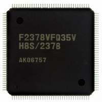
DF2378BVFQ35WV Renesas Electronics America, DF2378BVFQ35WV Datasheet - Page 1048

DF2378BVFQ35WV
Manufacturer Part Number
DF2378BVFQ35WV
Description
IC H8S/2378 MCU FLASH 144-QFP
Manufacturer
Renesas Electronics America
Series
H8® H8S/2300r
Datasheet
1.YR0K42378FC000BA.pdf
(1208 pages)
Specifications of DF2378BVFQ35WV
Core Processor
H8S/2000
Core Size
16-Bit
Speed
35MHz
Connectivity
I²C, IrDA, SCI, SmartCard
Peripherals
DMA, POR, PWM, WDT
Number Of I /o
97
Program Memory Size
512KB (512K x 8)
Program Memory Type
FLASH
Ram Size
32K x 8
Voltage - Supply (vcc/vdd)
3 V ~ 3.6 V
Data Converters
A/D 16x10b; D/A 6x8b
Oscillator Type
Internal
Operating Temperature
-40°C ~ 85°C
Package / Case
144-QFP
For Use With
EDK2378 - DEV EVAL KIT FOR H8S/2378
Lead Free Status / RoHS Status
Lead free / RoHS Compliant
Eeprom Size
-
Available stocks
Company
Part Number
Manufacturer
Quantity
Price
Company:
Part Number:
DF2378BVFQ35WV
Manufacturer:
Renesas Electronics America
Quantity:
10 000
- Current page: 1048 of 1208
- Download datasheet (8Mb)
Section 24 Power-Down Modes
24.4.3
Depending on the operating status of the EXDMAC, DMAC, or DTC, the MSTP14 to MSTP13
and may not be set to 1. Setting of the EXDMAC, DMAC, or DTC module stop mode should be
carried out only when the respective module is not activated.
For details, refer to section 8, EXDMA Controller (EXDMAC), section 7, DMA Controller
(DMAC), and section 9, Data Transfer Controller (DTC).
Note: The EXDMAC is not supported by the H8S/2375, H8S/2375R, H8S/2373, and
24.4.4
Relevant interrupt operations cannot be performed in module stop mode. Consequently, if module
stop mode is entered when an interrupt has been requested, it will not be possible to clear the CPU
interrupt source or the DMAC or DTC activation source.
Interrupts should therefore be disabled before entering module stop mode.
Note: The EXDMAC is not supported by the H8S/2375, H8S/2375R, H8S/2373, and
24.4.5
MSTPCR and EXMSTPCR should only be written to by the CPU.
24.4.6
The following points should be noted in clock division mode.
• Select the clock division ratio specified by the SCK2 to SCK0 bits so that the frequency of φ is
• All the on-chip peripheral modules operate on the φ. Therefore, note that the time processing
• Note that the frequency of φ will be changed by changing the clock division ratio.
Rev.7.00 Mar. 18, 2009 page 980 of 1136
REJ09B0109-0700
within the operation guaranteed range of clock cycle time tcyc shown in the Electrical
Characteristics. In other words, the range of φ must be specified to 8 MHz (min); outside of
this range (φ < 8 MHz) must be prevented.
of modules such as a timer and SCI differ before and after changing the clock division ratio. In
addition, wait time for clearing software standby mode differs by changing the clock division
ratio.
H8S/2373R.
H8S/2373R
EXDMAC, DMAC, and DTC Module Stop
On-Chip Peripheral Module Interrupts
Writing to MSTPCR, EXMSTPCR
Notes on Clock Division Mode
Related parts for DF2378BVFQ35WV
Image
Part Number
Description
Manufacturer
Datasheet
Request
R

Part Number:
Description:
KIT STARTER FOR M16C/29
Manufacturer:
Renesas Electronics America
Datasheet:

Part Number:
Description:
KIT STARTER FOR R8C/2D
Manufacturer:
Renesas Electronics America
Datasheet:

Part Number:
Description:
R0K33062P STARTER KIT
Manufacturer:
Renesas Electronics America
Datasheet:

Part Number:
Description:
KIT STARTER FOR R8C/23 E8A
Manufacturer:
Renesas Electronics America
Datasheet:

Part Number:
Description:
KIT STARTER FOR R8C/25
Manufacturer:
Renesas Electronics America
Datasheet:

Part Number:
Description:
KIT STARTER H8S2456 SHARPE DSPLY
Manufacturer:
Renesas Electronics America
Datasheet:

Part Number:
Description:
KIT STARTER FOR R8C38C
Manufacturer:
Renesas Electronics America
Datasheet:

Part Number:
Description:
KIT STARTER FOR R8C35C
Manufacturer:
Renesas Electronics America
Datasheet:

Part Number:
Description:
KIT STARTER FOR R8CL3AC+LCD APPS
Manufacturer:
Renesas Electronics America
Datasheet:

Part Number:
Description:
KIT STARTER FOR RX610
Manufacturer:
Renesas Electronics America
Datasheet:

Part Number:
Description:
KIT STARTER FOR R32C/118
Manufacturer:
Renesas Electronics America
Datasheet:

Part Number:
Description:
KIT DEV RSK-R8C/26-29
Manufacturer:
Renesas Electronics America
Datasheet:

Part Number:
Description:
KIT STARTER FOR SH7124
Manufacturer:
Renesas Electronics America
Datasheet:

Part Number:
Description:
KIT STARTER FOR H8SX/1622
Manufacturer:
Renesas Electronics America
Datasheet:

Part Number:
Description:
KIT DEV FOR SH7203
Manufacturer:
Renesas Electronics America
Datasheet:


