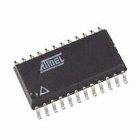
AT90PWM216-16SUR Atmel, AT90PWM216-16SUR Datasheet - Page 305

AT90PWM216-16SUR
Manufacturer Part Number
AT90PWM216-16SUR
Description
MCU AVR 16K FLASH 16MHZ 24SOIC
Manufacturer
Atmel
Series
AVR® 90PWM Lightingr
Datasheet
1.AT90PWM216-16SU.pdf
(359 pages)
Specifications of AT90PWM216-16SUR
Core Processor
AVR
Core Size
8-Bit
Speed
16MHz
Connectivity
SPI, UART/USART
Peripherals
Brown-out Detect/Reset, POR, PWM, WDT
Number Of I /o
19
Program Memory Size
16KB (16K x 8)
Program Memory Type
FLASH
Eeprom Size
512 x 8
Ram Size
1K x 8
Voltage - Supply (vcc/vdd)
2.7 V ~ 5.5 V
Data Converters
A/D 8x10b; D/A 1x10b
Oscillator Type
Internal
Operating Temperature
-40°C ~ 105°C
Package / Case
24-SOIC (7.5mm Width)
Processor Series
AT90PWMx
Core
AVR8
3rd Party Development Tools
EWAVR, EWAVR-BL
Development Tools By Supplier
ATAVRDRAGON, ATSTK500, ATSTK600, ATAVRISP2, ATAVRONEKIT, ATAVRFBKIT, ATAVRISP2
Lead Free Status / RoHS Status
Lead free / RoHS Compliant
- Current page: 305 of 359
- Download datasheet (6Mb)
26.6
7710E–AVR–08/10
SPI Timing Characteristics
See
Table 26-4.
Note:
Figure 26-3. SPI Interface Timing Requirements (Master Mode)
10
11
12
13
14
15
16
17
18
1
2
3
4
5
6
7
8
9
Figure 26-3
In SPI Programming mode the minimum SCK high/low period is:
- 2 t
- 3 t
(Data Output)
(Data Input)
(CPOL = 0)
(CPOL = 1)
CLCL
CLCL
SS high to tri-state
SCK to out high
SCK high/low
SCK to SS high
SS low to SCK
Rise/Fall time
Rise/Fall time
SCK high/low
SS low to out
SPI Timing Parameters
Description
MISO
MOSI
SCK period
SCK period
Out to SCK
SCK to out
SCK to out
for f
for f
SCK
SCK
and
SS
Setup
Setup
Hold
Hold
CK
CK
Figure 26-4
< 12 MHz
>12 MHz
(1)
6
4
MSB
5
for details.
MSB
Master
Master
Master
Master
Master
Master
Master
Master
Mode
Slave
Slave
Slave
Slave
Slave
Slave
Slave
Slave
Slave
Slave
7
4 • t
2 • t
2 • t
Min.
10
t
20
ck
...
ck
ck
ck
...
AT90PWM216/316
See
50% duty cycle
0.5 • t
Table 17-4
Typ.
3.6
10
10
15
10
10
15
10
2
sck
LSB
1
LSB
2
Max.
1.6
3
8
ns
305
Related parts for AT90PWM216-16SUR
Image
Part Number
Description
Manufacturer
Datasheet
Request
R

Part Number:
Description:
Manufacturer:
Atmel Corporation
Datasheet:

Part Number:
Description:
8-bit Microcontroller with 16K Bytes In-System Programmable flash
Manufacturer:
ATMEL [ATMEL Corporation]
Datasheet:

Part Number:
Description:
MCU AVR 16K ISP FLSH 16MHZ24SOIC
Manufacturer:
Atmel
Datasheet:

Part Number:
Description:
DEV KIT FOR AVR/AVR32
Manufacturer:
Atmel
Datasheet:

Part Number:
Description:
INTERVAL AND WIPE/WASH WIPER CONTROL IC WITH DELAY
Manufacturer:
ATMEL Corporation
Datasheet:

Part Number:
Description:
Low-Voltage Voice-Switched IC for Hands-Free Operation
Manufacturer:
ATMEL Corporation
Datasheet:

Part Number:
Description:
MONOLITHIC INTEGRATED FEATUREPHONE CIRCUIT
Manufacturer:
ATMEL Corporation
Datasheet:

Part Number:
Description:
AM-FM Receiver IC U4255BM-M
Manufacturer:
ATMEL Corporation
Datasheet:

Part Number:
Description:
Monolithic Integrated Feature Phone Circuit
Manufacturer:
ATMEL Corporation
Datasheet:

Part Number:
Description:
Multistandard Video-IF and Quasi Parallel Sound Processing
Manufacturer:
ATMEL Corporation
Datasheet:

Part Number:
Description:
High-performance EE PLD
Manufacturer:
ATMEL Corporation
Datasheet:

Part Number:
Description:
8-bit Flash Microcontroller
Manufacturer:
ATMEL Corporation
Datasheet:


