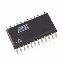
AT90PWM216-16SUR Atmel, AT90PWM216-16SUR Datasheet - Page 354

AT90PWM216-16SUR
Manufacturer Part Number
AT90PWM216-16SUR
Description
MCU AVR 16K FLASH 16MHZ 24SOIC
Manufacturer
Atmel
Series
AVR® 90PWM Lightingr
Datasheet
1.AT90PWM216-16SU.pdf
(359 pages)
Specifications of AT90PWM216-16SUR
Core Processor
AVR
Core Size
8-Bit
Speed
16MHz
Connectivity
SPI, UART/USART
Peripherals
Brown-out Detect/Reset, POR, PWM, WDT
Number Of I /o
19
Program Memory Size
16KB (16K x 8)
Program Memory Type
FLASH
Eeprom Size
512 x 8
Ram Size
1K x 8
Voltage - Supply (vcc/vdd)
2.7 V ~ 5.5 V
Data Converters
A/D 8x10b; D/A 1x10b
Oscillator Type
Internal
Operating Temperature
-40°C ~ 105°C
Package / Case
24-SOIC (7.5mm Width)
Processor Series
AT90PWMx
Core
AVR8
3rd Party Development Tools
EWAVR, EWAVR-BL
Development Tools By Supplier
ATAVRDRAGON, ATSTK500, ATSTK600, ATAVRISP2, ATAVRONEKIT, ATAVRFBKIT, ATAVRISP2
Lead Free Status / RoHS Status
Lead free / RoHS Compliant
- Current page: 354 of 359
- Download datasheet (6Mb)
iii
AT90PWM216/316
15 16-bit Timer/Counter1 with PWM ........................................................ 103
16 Power Stage Controller – (PSC0, PSC1 & PSC2) .............................. 131
14.6
14.7
14.8
15.1
15.2
15.3
15.4
15.5
15.6
15.7
15.8
15.9
15.10
16.1
16.2
16.3
16.4
16.5
16.6
16.7
16.8
16.9
16.10
16.11
16.12
16.13
16.14
16.15
16.16
16.17
16.18
16.19
16.20
Modes of Operation .........................................................................................91
Timer/Counter Timing Diagrams .....................................................................95
8-bit Timer/Counter Register Description ........................................................97
Overview ........................................................................................................103
Accessing 16-bit Registers ............................................................................105
Timer/Counter Clock Sources .......................................................................108
Counter Unit ..................................................................................................109
Input Capture Unit .........................................................................................110
Output Compare Units ...................................................................................112
Compare Match Output Unit ..........................................................................113
Modes of Operation .......................................................................................115
Timer/Counter Timing Diagrams ...................................................................122
16-bit Timer/Counter Register Description ....................................................124
Features ........................................................................................................131
Overview ........................................................................................................131
PSC Description ............................................................................................132
Signal Description ..........................................................................................134
Functional Description ...................................................................................136
Update of Values ...........................................................................................141
Enhanced Resolution ....................................................................................141
PSC Inputs ....................................................................................................145
PSC Input Mode 1: Stop signal, Jump to Opposite Dead-Time and Wait .....150
PSC Input Mode 2: Stop signal, Execute Opposite Dead-Time and Wait .....151
PSC Input Mode 3: Stop signal, Execute Opposite while Fault active ..........152
PSC Input Mode 4: Deactivate outputs without changing timing. ..................152
PSC Input Mode 5: Stop signal and Insert Dead-Time ..................................153
PSC Input Mode 6: Stop signal, Jump to Opposite Dead-Time and Wait. ....154
PSC Input Mode 7: Halt PSC and Wait for Software Action ..........................154
PSC Input Mode 8: Edge Retrigger PSC .......................................................154
PSC Input Mode 9: Fixed Frequency Edge Retrigger PSC ...........................155
PSC Input Mode 14: Fixed Frequency Edge Retrigger PSC and Disactivate Out-
put 156
PSC2 Outputs ................................................................................................159
Analog Synchronization .................................................................................159
7710E–AVR–08/10
Related parts for AT90PWM216-16SUR
Image
Part Number
Description
Manufacturer
Datasheet
Request
R

Part Number:
Description:
Manufacturer:
Atmel Corporation
Datasheet:

Part Number:
Description:
8-bit Microcontroller with 16K Bytes In-System Programmable flash
Manufacturer:
ATMEL [ATMEL Corporation]
Datasheet:

Part Number:
Description:
MCU AVR 16K ISP FLSH 16MHZ24SOIC
Manufacturer:
Atmel
Datasheet:

Part Number:
Description:
DEV KIT FOR AVR/AVR32
Manufacturer:
Atmel
Datasheet:

Part Number:
Description:
INTERVAL AND WIPE/WASH WIPER CONTROL IC WITH DELAY
Manufacturer:
ATMEL Corporation
Datasheet:

Part Number:
Description:
Low-Voltage Voice-Switched IC for Hands-Free Operation
Manufacturer:
ATMEL Corporation
Datasheet:

Part Number:
Description:
MONOLITHIC INTEGRATED FEATUREPHONE CIRCUIT
Manufacturer:
ATMEL Corporation
Datasheet:

Part Number:
Description:
AM-FM Receiver IC U4255BM-M
Manufacturer:
ATMEL Corporation
Datasheet:

Part Number:
Description:
Monolithic Integrated Feature Phone Circuit
Manufacturer:
ATMEL Corporation
Datasheet:

Part Number:
Description:
Multistandard Video-IF and Quasi Parallel Sound Processing
Manufacturer:
ATMEL Corporation
Datasheet:

Part Number:
Description:
High-performance EE PLD
Manufacturer:
ATMEL Corporation
Datasheet:

Part Number:
Description:
8-bit Flash Microcontroller
Manufacturer:
ATMEL Corporation
Datasheet:


