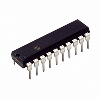
PIC16C781-I/P Microchip Technology, PIC16C781-I/P Datasheet - Page 106

PIC16C781-I/P
Manufacturer Part Number
PIC16C781-I/P
Description
IC MCU OTP 1KX14 W/AD COMP 20DIP
Manufacturer
Microchip Technology
Series
PIC® 16Cr
Datasheets
1.PIC16C781-ISO.pdf
(186 pages)
2.PIC16C781-ISO.pdf
(8 pages)
3.PIC16C781-ISO.pdf
(8 pages)
Specifications of PIC16C781-I/P
Core Size
8-Bit
Program Memory Size
1.75KB (1K x 14)
Core Processor
PIC
Speed
20MHz
Peripherals
Brown-out Detect/Reset, POR, PWM, WDT
Number Of I /o
13
Program Memory Type
OTP
Ram Size
128 x 8
Voltage - Supply (vcc/vdd)
4 V ~ 5.5 V
Data Converters
A/D 8x8b; D/A 1x8b
Oscillator Type
Internal
Operating Temperature
-40°C ~ 85°C
Package / Case
20-DIP (0.300", 7.62mm)
Controller Family/series
PIC16C
No. Of I/o's
16
Ram Memory Size
128Byte
Cpu Speed
20MHz
No. Of Timers
3
Processor Series
PIC16C
Core
PIC
Data Bus Width
8 bit
Data Ram Size
128 B
Maximum Clock Frequency
20 MHz
Number Of Programmable I/os
16
Number Of Timers
2
Operating Supply Voltage
2.5 V to 5.5 V
Maximum Operating Temperature
+ 85 C
Mounting Style
Through Hole
3rd Party Development Tools
52715-96, 52716-328, 52717-734
Development Tools By Supplier
ICE2000, DM163022
Minimum Operating Temperature
- 40 C
On-chip Adc
8 bit
On-chip Dac
8 bit, 1 Channel
Lead Free Status / RoHS Status
Lead free / RoHS Compliant
For Use With
ISPICR1 - ADAPTER IN-CIRCUIT PROGRAMMINGDVA16XP202 - ADAPTER DEVICE PIC16C781/782DM163012 - BOARD DEMO PICDEM FOR 16C781/782AC164028 - MODULE SKT PROMATEII 20SOIC/DIP
Eeprom Size
-
Connectivity
-
Lead Free Status / Rohs Status
Details
Other names
PIC16C781I/P
PIC16C781/782
13.2
The PSMC is controlled by means of two special func-
tion registers: PSMCCON0 and PSMCCON1.
The PSMCCON0 register (Register 13-1) contains
control bits for:
• Frequency of the output pulse
• Minimum and maximum duty cycle in PWM mode
• Fixed duty cycle in PSM mode
The PSMCCON1 register (Register 13-2) contains the
control bits for:
• Enabling the PSMC module
• Setting the PSMC mode
• Configuring inputs and outputs
13.2.1
The SMCCL<1:0> bits in the PSMCCON0 register, are
used to set the pulse frequency of the PSMC.
In
(PSMCCON0 <5:4>) specify the minimum duty cycle.
TABLE 13-5:
Legend: x = Don’t Care
*As needed for other functions (such as C2, RB7, T1G).
DS41171A-page 104
Single Output
Single Output + Slope Compensation
Dual Output
Note:
Note:
the
Control Registers
PWM
Following RESET, both the PSMC1A and
PSMC1B outputs are held tri-state until the
PSMC is configured. Driver circuitry for all
power MOSFET transistors must have a
resistor bias to turn off the transistor in the
event of tri-state conditions, on either
PSMC1A or PSMC1B, to prevent exces-
sive stress on the MOSFET's and their
associated circuitry.
Changing SMCCL<1:0> bits with the
PSMC enabled (SMCON=1) can result in
unpredictable
PSMC before changing SMCCL<1:0>.
PSMCCON0 REGISTER
FUNCTION
mode,
PSMC OUTPUT MODES
the
output.
MINDC
Always
<1:0>
disable
SMCOM
0
0
1
Preliminary
bits
PSMC
In
(PSMCCON0 <3:2>) specify the maximum duty cycle
limit.
In
(PSMCCON0<1:0>) specify the fixed duty cycle.
13.2.2
To enable the PSMC operation, the SMCON bit in the
PSMCCON1 register must be set (see Register 13-2).
The PWM/PSM bit (PSMCCON1<1>) configures the
output mode of the PSMC. When the PWM/PSM bit is
set, the PSMC is configured for a PWM output. When
the PWM/PSM bit is cleared, a fixed duty cycle pulse is
output.
The SMCCS bit (PSMCCON1<0>) sets the input
mode. When the SMCCS bit is set, the PSMC is con-
figured for two inputs: C1 and C2. When cleared, only
Comparator C1 is used.
SMCOM bit (PSMCCON1<1>) determines the number
of outputs from the PSMC. When SMCOM is set, both
PSMC1A and PSMC1B are active. When SMCOM is
cleared, only the PSMC1A output is active and the
PSMC1B output is available for another function.
S1APOL and S1BPOL control the polarity of the PSMC
outputs. Setting the polarity bit configures the corre-
sponding output for an active low state. Clearing the bit
results in an active high output.
The SCEN bit (PSMCCON1<2>) enables the slope
compensation output. When SCEN is set (and SMCOM
is cleared) the PSMC1B output is configured to gener-
ate a slope compensation signal.
Note:
SCEN
the
0
1
x
the
PWM
PSMC outputs must have their corre-
sponding direction bits cleared in TRISB;
TRISB<6>: for PSMC1A, and TRISB<7>
for PSMC1B.
PSMCCON1 REGISTER
PSM
mode,
TRISB<6>
mode,
0
0
0
2001 Microchip Technology Inc.
the
PORTB
the
MAXDC
DC<1:0>
TRISB<7>
<1:0>
0
0
*
bits
bits


