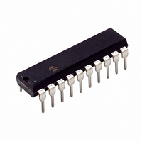
PIC16C781-I/P Microchip Technology, PIC16C781-I/P Datasheet - Page 111

PIC16C781-I/P
Manufacturer Part Number
PIC16C781-I/P
Description
IC MCU OTP 1KX14 W/AD COMP 20DIP
Manufacturer
Microchip Technology
Series
PIC® 16Cr
Datasheets
1.PIC16C781-ISO.pdf
(186 pages)
2.PIC16C781-ISO.pdf
(8 pages)
3.PIC16C781-ISO.pdf
(8 pages)
Specifications of PIC16C781-I/P
Core Size
8-Bit
Program Memory Size
1.75KB (1K x 14)
Core Processor
PIC
Speed
20MHz
Peripherals
Brown-out Detect/Reset, POR, PWM, WDT
Number Of I /o
13
Program Memory Type
OTP
Ram Size
128 x 8
Voltage - Supply (vcc/vdd)
4 V ~ 5.5 V
Data Converters
A/D 8x8b; D/A 1x8b
Oscillator Type
Internal
Operating Temperature
-40°C ~ 85°C
Package / Case
20-DIP (0.300", 7.62mm)
Controller Family/series
PIC16C
No. Of I/o's
16
Ram Memory Size
128Byte
Cpu Speed
20MHz
No. Of Timers
3
Processor Series
PIC16C
Core
PIC
Data Bus Width
8 bit
Data Ram Size
128 B
Maximum Clock Frequency
20 MHz
Number Of Programmable I/os
16
Number Of Timers
2
Operating Supply Voltage
2.5 V to 5.5 V
Maximum Operating Temperature
+ 85 C
Mounting Style
Through Hole
3rd Party Development Tools
52715-96, 52716-328, 52717-734
Development Tools By Supplier
ICE2000, DM163022
Minimum Operating Temperature
- 40 C
On-chip Adc
8 bit
On-chip Dac
8 bit, 1 Channel
Lead Free Status / RoHS Status
Lead free / RoHS Compliant
For Use With
ISPICR1 - ADAPTER IN-CIRCUIT PROGRAMMINGDVA16XP202 - ADAPTER DEVICE PIC16C781/782DM163012 - BOARD DEMO PICDEM FOR 16C781/782AC164028 - MODULE SKT PROMATEII 20SOIC/DIP
Eeprom Size
-
Connectivity
-
Lead Free Status / Rohs Status
Details
Other names
PIC16C781I/P
EXAMPLE 13-1:
;* This code block will configure the PSMC and
;*
;*
;*
;*
;*
;*
;*
;*
;*
;*
**********************************************************
;*
;**********************************************************************
;*
;*
;**********************************************************************
;*
;*
;*************************************************************************
;*
;*
;*
;************************************************************************
;*
;*
;*
2001 Microchip Technology Inc.
Order of configuration
1.
2.
3.
4.
5.
6.
This code block will configure all analog ports.
BANKSEL
MOVLW
MOVWF
MOVLW
MOVWF
MOVLW
MOVWF
This code block will configure the DAC for VDD as
DACREF, and RB1/AN5/VDAC as an output
BANKSEL
CLRF
MOVLW
MOVWF
MOVLW
MOVWF
This code block will configure the OPA module as an
Op Amp, with a 2MHz GBWP
MOVLW
MOVWF
This code block will configure Comparator C1
for normal speed and output polarity,
input on AN6, and Reference from the VREF1
MOVLW
MOVWF
This code block will configure the PSMC module
for PWM, FOSC/128, Single in, Single pulse out, slope comp out
Non-inverting out, DC min = 0%, DC max = 75%
MOVLW
MOVWF
MOVLW
MOVWF
BSF
all additional peripherals for a boost mode
switching power supply.
PORTA/B I/O and analog configured
DAC enabled, configured, and preset
Op Amp enabled and configured
Comparator C1 enabled and configured
PSMC configured
PSMC enabled
TRISA
B’00001011’
TRISA
B’11001110’
TRISB
B’11101011’
ANSEL
DACON0
DAC
B’11000000’
DACON0
OUTPUT_VALUE
DAC
B’10000001’
OPACON
B’10001010
CM1CON0
B’00001000’
PSMCCON0
B’00001010’
PSMCCON1
PSMCCON1,SMCON
PSMC CONFIGURATION EXAMPLE
; Select Bank 1
; Set RA0,1,& 3 as inputs
; Set RB1,2,3,6 & 7 as inputs
; Configure RA0, RA1, RA3,
; RB1, RB2, RB3 as analog
; Select Bank 2
; Set DAC to safe value
; Enable DAC, output
;
; Set DAC output level
; Set Op Amp mode and
;
; Set C1, no ext out, norm
;
; Set DCmin 0, DCmax 75, FOSC/128
; Set PWM Sngl in, Sngl out non-invert
; Slope comp
; Enable PSMC
2MHz GBWP
and set DACREF = VDD
speed & pol, VREF1, AN6
Preliminary
PIC16C781/782
DS41171A-page 109


