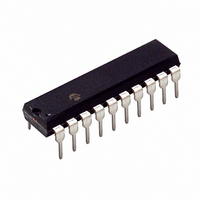
PIC16C781-I/P Microchip Technology, PIC16C781-I/P Datasheet - Page 54

PIC16C781-I/P
Manufacturer Part Number
PIC16C781-I/P
Description
IC MCU OTP 1KX14 W/AD COMP 20DIP
Manufacturer
Microchip Technology
Series
PIC® 16Cr
Datasheets
1.PIC16C781-ISO.pdf
(186 pages)
2.PIC16C781-ISO.pdf
(8 pages)
3.PIC16C781-ISO.pdf
(8 pages)
Specifications of PIC16C781-I/P
Core Size
8-Bit
Program Memory Size
1.75KB (1K x 14)
Core Processor
PIC
Speed
20MHz
Peripherals
Brown-out Detect/Reset, POR, PWM, WDT
Number Of I /o
13
Program Memory Type
OTP
Ram Size
128 x 8
Voltage - Supply (vcc/vdd)
4 V ~ 5.5 V
Data Converters
A/D 8x8b; D/A 1x8b
Oscillator Type
Internal
Operating Temperature
-40°C ~ 85°C
Package / Case
20-DIP (0.300", 7.62mm)
Controller Family/series
PIC16C
No. Of I/o's
16
Ram Memory Size
128Byte
Cpu Speed
20MHz
No. Of Timers
3
Processor Series
PIC16C
Core
PIC
Data Bus Width
8 bit
Data Ram Size
128 B
Maximum Clock Frequency
20 MHz
Number Of Programmable I/os
16
Number Of Timers
2
Operating Supply Voltage
2.5 V to 5.5 V
Maximum Operating Temperature
+ 85 C
Mounting Style
Through Hole
3rd Party Development Tools
52715-96, 52716-328, 52717-734
Development Tools By Supplier
ICE2000, DM163022
Minimum Operating Temperature
- 40 C
On-chip Adc
8 bit
On-chip Dac
8 bit, 1 Channel
Lead Free Status / RoHS Status
Lead free / RoHS Compliant
For Use With
ISPICR1 - ADAPTER IN-CIRCUIT PROGRAMMINGDVA16XP202 - ADAPTER DEVICE PIC16C781/782DM163012 - BOARD DEMO PICDEM FOR 16C781/782AC164028 - MODULE SKT PROMATEII 20SOIC/DIP
Eeprom Size
-
Connectivity
-
Lead Free Status / Rohs Status
Details
Other names
PIC16C781I/P
PIC16C781/782
5.2
An 8-bit counter is available as a prescaler for the
Timer0 module, or as a postscaler for the Watchdog
Timer, respectively (Figure 5-2). For simplicity, this
counter is referred to as “prescaler” throughout this
data sheet.
The prescaler is not readable or writable.
The PSA and PS<2:0> bits (OPTION_REG<3:0>)
determine the prescaler assignment and prescale ratio.
Clearing bit PSA assigns the prescaler to the Timer0
module. When the prescaler is assigned to the Timer0
module, prescale values of 1:2, 1:4, ..., 1:256 are
selectable.
Setting bit PSA assigns the prescaler to the Watchdog
Timer (WDT). When the prescaler is assigned to the
WDT, prescale values of 1:1, 1:2, ..., 1:128 are selectable.
When assigned to the Timer0 module, all instructions
writing to the TMR0 register (e.g.,
MOVWF TMR0, BSF TMR0, x....etc.) will clear the
prescaler. When assigned to WDT, a CLRWDT instruc-
tion clears the prescaler along with the WDT.
DS41171A-page 52
Note:
Note:
Prescaler
There is only one prescaler available
which is mutually exclusively shared
between the Timer0 module and the
Watchdog Timer. Thus, a prescaler assign-
ment for the Timer0 module means that
there is no prescaler for the Watchdog
Timer, and vice-versa.
Writing to TMR0 when the prescaler is
assigned to Timer0 clears the prescaler
count, but does not change the prescaler
assignment.
CLRF
TMR0,
Preliminary
5.2.1
The prescaler assignment is fully under software con-
trol, i.e., it can be changed “on-the-fly” during program
execution.
5.3
The TMR0 interrupt is generated when the TMR0 reg-
ister overflows from FFh to 00h. This overflow sets bit
T0IF (INTCON<2>). The interrupt can be masked by
clearing bit T0IE (INTCON<5>). Bit T0IF must be
cleared in software by the Timer0 module Interrupt Ser-
vice Routine before re-enabling this interrupt. The
TMR0 interrupt cannot awaken the processor from
SLEEP, since the timer is shut-off during SLEEP.
5.4
A device RESET will program Timer0 for an external
clock input on RA4/T0CKI, Hi-Low edge, and no pres-
caler. The TMR0 register is not cleared.
Note:
Timer0 Interrupt
Effects of RESET
To avoid an unintended device RESET, a
specific instruction sequence (shown in the
PICmicro™ Mid-Range Reference Man-
ual, DS33023) must be executed when
changing the prescaler assignment from
Timer0 to the WDT. This sequence must
be followed even if the WDT is disabled.
SWITCHING PRESCALER
ASSIGNMENT
2001 Microchip Technology Inc.


