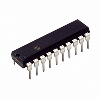
PIC16C781-I/P Microchip Technology, PIC16C781-I/P Datasheet - Page 86

PIC16C781-I/P
Manufacturer Part Number
PIC16C781-I/P
Description
IC MCU OTP 1KX14 W/AD COMP 20DIP
Manufacturer
Microchip Technology
Series
PIC® 16Cr
Datasheets
1.PIC16C781-ISO.pdf
(186 pages)
2.PIC16C781-ISO.pdf
(8 pages)
3.PIC16C781-ISO.pdf
(8 pages)
Specifications of PIC16C781-I/P
Core Size
8-Bit
Program Memory Size
1.75KB (1K x 14)
Core Processor
PIC
Speed
20MHz
Peripherals
Brown-out Detect/Reset, POR, PWM, WDT
Number Of I /o
13
Program Memory Type
OTP
Ram Size
128 x 8
Voltage - Supply (vcc/vdd)
4 V ~ 5.5 V
Data Converters
A/D 8x8b; D/A 1x8b
Oscillator Type
Internal
Operating Temperature
-40°C ~ 85°C
Package / Case
20-DIP (0.300", 7.62mm)
Controller Family/series
PIC16C
No. Of I/o's
16
Ram Memory Size
128Byte
Cpu Speed
20MHz
No. Of Timers
3
Processor Series
PIC16C
Core
PIC
Data Bus Width
8 bit
Data Ram Size
128 B
Maximum Clock Frequency
20 MHz
Number Of Programmable I/os
16
Number Of Timers
2
Operating Supply Voltage
2.5 V to 5.5 V
Maximum Operating Temperature
+ 85 C
Mounting Style
Through Hole
3rd Party Development Tools
52715-96, 52716-328, 52717-734
Development Tools By Supplier
ICE2000, DM163022
Minimum Operating Temperature
- 40 C
On-chip Adc
8 bit
On-chip Dac
8 bit, 1 Channel
Lead Free Status / RoHS Status
Lead free / RoHS Compliant
For Use With
ISPICR1 - ADAPTER IN-CIRCUIT PROGRAMMINGDVA16XP202 - ADAPTER DEVICE PIC16C781/782DM163012 - BOARD DEMO PICDEM FOR 16C781/782AC164028 - MODULE SKT PROMATEII 20SOIC/DIP
Eeprom Size
-
Connectivity
-
Lead Free Status / Rohs Status
Details
Other names
PIC16C781I/P
PIC16C781/782
REGISTER 11-1:
11.1.2
The Automatic Calibration Module (ACM) is an internal
state machine which performs an input offset voltage
calibration (trim) on the OPA module (see Figure 11-2).
Calibration is initiated by setting the CAL bit
(CALCON<7>). Upon completion of the calibration
sequence, the ACM will clear the CAL bit.
If a problem arises in the calibration process, the
CALERR flag (CALCON<6>) will be set to indicate the
failure to calibrate.
Setting CALREF (CALCON<5>) forces calibration at a
common mode voltage specified by the output of the
DAC module. The DAC module must be enabled prior
to calibration. Clearing CALREF will perform the cali-
bration with a common mode voltage of 1.2V. The out-
put pin floats during calibration.
DS41171A-page 84
bit 7
bit 6
bit 5-1
bit 0
CALCON REGISTER
OPAMP CONTROL REGISTER (OPACON: 11Ch)
OPAON: OPAMP Enable bit
1 = OPAMP is enabled
0 = OPAMP is disabled
CMPEN: Comparator Mode Enable bit
1 = Comparator mode
0 = OPAMP mode
Unimplemented: Read as ’0’
GBWP: Gain Bandwidth Product Select bits
1 = 2 MHz typ. (fast mode)
0 = 70 kHz typ. (slow mode)
Legend:
R = Readable bit
- n = Value at POR
bit 7
OPAON
R/W-0
CMPEN
R/W-0
Preliminary
U-0
W = Writable bit
’1’ = Bit is set
—
U-0
—
Note 1: Auto Calibration must be performed while
2: If the internal 1.2V reference is used for
3: The OPA module shares pins with the
4: When using the DAC as a reference for
U = Unimplemented bit, read as ‘0’
’0’ = Bit is cleared
U-0
the module is configured as an OPAMP
(CMPEN = 0). Performing Auto Calibra-
tion function in the Comparator mode
may yield unpredictable results.
the common mode voltage during Auto
Calibration, CALREF = 0 (CALCON<5>),
a delay for reference stabilization must be
observed before start of calibration.
ADC module. Performing ADC conver-
sions on the OPA+ or OPA- pins may
affect OPAMP stability.
calibration, CALREF = 1 (CALCON<5>),
the V
ified common mode voltage for the
OPAMP.
—
DAC
voltage must be within the spec-
U-0
—
2001 Microchip Technology Inc.
x = Bit is unknown
U-0
—
GBWP
R/W-0
bit 0


