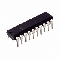
PIC16C781-I/P Microchip Technology, PIC16C781-I/P Datasheet - Page 37

PIC16C781-I/P
Manufacturer Part Number
PIC16C781-I/P
Description
IC MCU OTP 1KX14 W/AD COMP 20DIP
Manufacturer
Microchip Technology
Series
PIC® 16Cr
Datasheets
1.PIC16C781-ISO.pdf
(186 pages)
2.PIC16C781-ISO.pdf
(8 pages)
3.PIC16C781-ISO.pdf
(8 pages)
Specifications of PIC16C781-I/P
Core Size
8-Bit
Program Memory Size
1.75KB (1K x 14)
Core Processor
PIC
Speed
20MHz
Peripherals
Brown-out Detect/Reset, POR, PWM, WDT
Number Of I /o
13
Program Memory Type
OTP
Ram Size
128 x 8
Voltage - Supply (vcc/vdd)
4 V ~ 5.5 V
Data Converters
A/D 8x8b; D/A 1x8b
Oscillator Type
Internal
Operating Temperature
-40°C ~ 85°C
Package / Case
20-DIP (0.300", 7.62mm)
Controller Family/series
PIC16C
No. Of I/o's
16
Ram Memory Size
128Byte
Cpu Speed
20MHz
No. Of Timers
3
Processor Series
PIC16C
Core
PIC
Data Bus Width
8 bit
Data Ram Size
128 B
Maximum Clock Frequency
20 MHz
Number Of Programmable I/os
16
Number Of Timers
2
Operating Supply Voltage
2.5 V to 5.5 V
Maximum Operating Temperature
+ 85 C
Mounting Style
Through Hole
3rd Party Development Tools
52715-96, 52716-328, 52717-734
Development Tools By Supplier
ICE2000, DM163022
Minimum Operating Temperature
- 40 C
On-chip Adc
8 bit
On-chip Dac
8 bit, 1 Channel
Lead Free Status / RoHS Status
Lead free / RoHS Compliant
For Use With
ISPICR1 - ADAPTER IN-CIRCUIT PROGRAMMINGDVA16XP202 - ADAPTER DEVICE PIC16C781/782DM163012 - BOARD DEMO PICDEM FOR 16C781/782AC164028 - MODULE SKT PROMATEII 20SOIC/DIP
Eeprom Size
-
Connectivity
-
Lead Free Status / Rohs Status
Details
Other names
PIC16C781I/P
3.3
PORTB is an 8-bit wide, bi-directional port. The corre-
sponding data direction register is TRISB. Setting a
TRISB bit (= 1) makes the corresponding PORTB pin
an input (i.e., puts the corresponding output driver into
a Hi-Impedance mode). Clearing a TRISB bit (= 0)
makes the corresponding PORTB pin an output (i.e.,
puts the contents of the output latch on the selected
pin.
EXAMPLE 3-2:
;* This code block will configure PORT B
;* as follows
;*
;*
;*
;*
;*
The RB0 pin can be configured as:
• Digital I/O
• ADC/Comparator Analog Input (AN4)
• External Interrupt (INT)
• Voltage Reference Output (V
When the pin is used as an analog I/O, the ANSEL reg-
ister must have bit 4 set to configure the RB0 pin as an
analog input.
Pin RB1 is multiplexed with two analog functions: ADC/
Comparator Analog Input AN5, and the output of the
DAC. When the pin is used as an analog I/O, the
ANSEL register must have bit 5 set to configure the
RB1 pin as an analog I/O.
2001 Microchip Technology Inc.
RB<7:6> analog inputs
RB<5:4> digital inputs
RB<3:2> digital inputs
RB<1:0> digital inputs
RA<3:0> digital I/O
BANKSEL
CLRF
BANKSEL
MOVLW
MOVWF
MOVLW
MOVWF
PORTB and the TRISB Register
PORTB
PORTB
TRISB
B’11001111’ ; Digital I/O
TRISB
B’00000011’ ; Analog I/O config
ANSEL
INITIALIZING PORTB
R
; Select Bank 0
; Preset PORTB data
; reg.
; Select Bank 1
;
; Configure PORTB
; digital
; data
; Configure PORTB
; analog
)
config data
Preliminary
Pin RB2 is multiplexed with the analog function ADC/
Comparator Input AN6. When the pin is used as an
analog input, the ANSEL register must have bit 6 to
select the Analog mode for the pin.
The RB3 pin is multiplexed with two analog functions:
ADC/Comparator Analog Input AN7, and the output of
the OPA module. When the pin is used as analog I/O,
the ANSEL register must have bit 7 set to select the
Analog mode of the pin.
Pins RB<7:6> are multiplexed with the outputs of the
two on-board comparators, the outputs of the PSMC
module, and the clock gate input for Timer1. Note,
when enabled, these peripherals override the PORTB
data register; however, TRISB retains control of output
drivers. Therefore, TRISB<7:6> must be programmed
appropriately for Comparator and PSMC outputs to
operate.
3.3.1
Each of the PORTB pins has an internal weak pull-up
resistance, which can be individually enabled from the
WPUB register. A single global enable bit, RBPU
(OPTION_REG<7>), can turn on/off all of the selected
pull-ups. Clearing the RBPU bit (OPTION_REG<7>)
enables the weak pull-up resistors (see Register 3-2).
The weak pull-up is automatically turned off when the
port pin is configured as an output. The pull-ups are dis-
abled on a Power-on Reset.
3.3.2
Each of the PORTB pins, if configured as input, has the
ability to generate an interrupt-on-change. To enable
the interrupt-on-change feature, the corresponding bit
must be set in the IOCB register (see Register 3-3).
The RBIE bit in the INTCON register functions as a glo-
bal enable bit to turn on/off the interrupt-on-change fea-
ture. The selected inputs are compared to the old value
latched on the last read of PORTB. The ”mismatch”
outputs are OR-ed together to generate the RB Port
Change Interrupt with flag bit RBIF (INTCON<0>).
The IOCB interrupt can also awaken the device from
SLEEP. The user, in the Interrupt Service Routine,
must clear the interrupt in the following manner:
a)
b)
A read or write to PORTB. This copies the cur-
rent state into the latch and ends the mismatch
condition.
Clear flag bit RBIF.
PORTB WEAK PULL-UP
PORTB INTERRUPT-ON-CHANGE
PIC16C781/782
DS41171A-page 35


