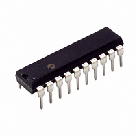
PIC16C781-I/P Microchip Technology, PIC16C781-I/P Datasheet - Page 131

PIC16C781-I/P
Manufacturer Part Number
PIC16C781-I/P
Description
IC MCU OTP 1KX14 W/AD COMP 20DIP
Manufacturer
Microchip Technology
Series
PIC® 16Cr
Datasheets
1.PIC16C781-ISO.pdf
(186 pages)
2.PIC16C781-ISO.pdf
(8 pages)
3.PIC16C781-ISO.pdf
(8 pages)
Specifications of PIC16C781-I/P
Core Size
8-Bit
Program Memory Size
1.75KB (1K x 14)
Core Processor
PIC
Speed
20MHz
Peripherals
Brown-out Detect/Reset, POR, PWM, WDT
Number Of I /o
13
Program Memory Type
OTP
Ram Size
128 x 8
Voltage - Supply (vcc/vdd)
4 V ~ 5.5 V
Data Converters
A/D 8x8b; D/A 1x8b
Oscillator Type
Internal
Operating Temperature
-40°C ~ 85°C
Package / Case
20-DIP (0.300", 7.62mm)
Controller Family/series
PIC16C
No. Of I/o's
16
Ram Memory Size
128Byte
Cpu Speed
20MHz
No. Of Timers
3
Processor Series
PIC16C
Core
PIC
Data Bus Width
8 bit
Data Ram Size
128 B
Maximum Clock Frequency
20 MHz
Number Of Programmable I/os
16
Number Of Timers
2
Operating Supply Voltage
2.5 V to 5.5 V
Maximum Operating Temperature
+ 85 C
Mounting Style
Through Hole
3rd Party Development Tools
52715-96, 52716-328, 52717-734
Development Tools By Supplier
ICE2000, DM163022
Minimum Operating Temperature
- 40 C
On-chip Adc
8 bit
On-chip Dac
8 bit, 1 Channel
Lead Free Status / RoHS Status
Lead free / RoHS Compliant
For Use With
ISPICR1 - ADAPTER IN-CIRCUIT PROGRAMMINGDVA16XP202 - ADAPTER DEVICE PIC16C781/782DM163012 - BOARD DEMO PICDEM FOR 16C781/782AC164028 - MODULE SKT PROMATEII 20SOIC/DIP
Eeprom Size
-
Connectivity
-
Lead Free Status / Rohs Status
Details
Other names
PIC16C781I/P
14.9.2
An overflow (FFh
flag bit, T0IF (INTCON<2>). The interrupt can be
enabled/disabled by setting/clearing enable bit, T0IE
(INTCON<5>) (Section 2.5).
14.9.3
An input change on PORTB<7:0> sets flag bit RBIF
(INTCON<0>). The PORTB pin(s) which can individu-
ally generate interrupt are selectable in the IOCB regis-
ter. The interrupt can be enabled/disabled by setting/
clearing enable bit RBIE (INTCON<4>) (Section 2.5).
PORTB must be configured as a digital input.
14.10 Context Saving During Interrupts
During an interrupt, only the PC is saved on the stack.
At minimum, W and STATUS should be saved to pre-
serve the context for the interrupted program. All regis-
ters that may be corrupted by the Interrupt Service
Routine (ISR), such as PCLATH or FSR, should be
saved.
Example 14-1 stores and restores the STATUS, W and
PCLATH registers. The register, W_TEMP, is defined in
Common RAM, the last 16 bytes of each bank that may
be accessed from any bank. The STATUS_TEMP and
PCLATH_TEMP are defined in bank 0.
The example:
a)
b)
c)
d)
e)
f)
g)
Note:
2001 Microchip Technology Inc.
Stores the W register.
Stores the STATUS register in bank 0.
Stores the PCLATH register in bank 0.
Executes the ISR code.
Restores the PCLATH register.
Restores the STATUS register.
Restores W.
The
PCLATH_TEMP are defined in the com-
mon RAM area (70h - 7Fh) to avoid regis-
ter bank switching during context save and
restore.
TMR0 INTERRUPT
PORTB INTERRUPT-ON-CHANGE
(IOCB)
W_TEMP,
00h) in the TMR0 register sets the
STATUS_TEMP
and
Preliminary
EXAMPLE 14-1:
#define
#define
#define
14.11 Watchdog Timer (WDT)
The Watchdog Timer uses a free running, on-chip RC
oscillator, which does not require any external compo-
nents. This oscillator is independent from the processor
clock. The WDT runs even if the main clock of the
device has been stopped (for example, by execution of
a SLEEP instruction).
During normal operation, a WDT time-out generates a
device RESET (Watchdog Timer Reset). If the device is
in SLEEP mode, a WDT time-out causes the device to
wake-up and continue with normal operation (Watch-
dog Timer Wake-up). The TO bit in the STATUS regis-
ter is cleared upon a Watchdog Timer time-out.
The WDT can be permanently enabled by program-
ming the configuration bit WDTE, or by software via the
WDTON bit in the Power Control register (PCON:
8EH). See Section 14.8 and Section 14.1.
WDT time-out period values may be found in the Elec-
trical Specifications. Values for the WDT prescaler may
be assigned using the OPTION_REG register.
Note 1: The CLRWDT and SLEEP instructions
org
MOVWF
MOVF
MOVWF
MOVF
MOVWF
:
(Interrupt Service Routine)
:
MOVF
MOVWF
MOVF
MOVWF
SWAPF
SWAPF
RETFIE
2: When a CLRWDT instruction is executed
clear the WDT and the postscaler, if
assigned to the WDT.
and the prescaler is assigned to the WDT,
the prescaler count is cleared, but the
prescaler assignment is not changed.
W_TEMP
STATUS_TEMP
PCLATH_TEMP
0x04
STATUS,w
STATUS_TEMP
PCLATH,w
PCLATH_TEMP
PCLATH_TEMP,w
PCLATH
STATUS_TEMP,w
STATUS
W_TEMP,f
W_TEMP,w
W_TEMP
PIC16C781/782
SAVING STATUS, W, AND
PCLATH REGISTERS
0x70
0x71
0x72
; Int Vector
; Save W
; save STATUS
; save PCLATH
; swapf loads W
; w/o affect STATUS
DS41171A-page 129


