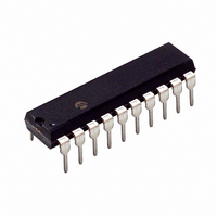
PIC16C781-I/P Microchip Technology, PIC16C781-I/P Datasheet - Page 122

PIC16C781-I/P
Manufacturer Part Number
PIC16C781-I/P
Description
IC MCU OTP 1KX14 W/AD COMP 20DIP
Manufacturer
Microchip Technology
Series
PIC® 16Cr
Datasheets
1.PIC16C781-ISO.pdf
(186 pages)
2.PIC16C781-ISO.pdf
(8 pages)
3.PIC16C781-ISO.pdf
(8 pages)
Specifications of PIC16C781-I/P
Core Size
8-Bit
Program Memory Size
1.75KB (1K x 14)
Core Processor
PIC
Speed
20MHz
Peripherals
Brown-out Detect/Reset, POR, PWM, WDT
Number Of I /o
13
Program Memory Type
OTP
Ram Size
128 x 8
Voltage - Supply (vcc/vdd)
4 V ~ 5.5 V
Data Converters
A/D 8x8b; D/A 1x8b
Oscillator Type
Internal
Operating Temperature
-40°C ~ 85°C
Package / Case
20-DIP (0.300", 7.62mm)
Controller Family/series
PIC16C
No. Of I/o's
16
Ram Memory Size
128Byte
Cpu Speed
20MHz
No. Of Timers
3
Processor Series
PIC16C
Core
PIC
Data Bus Width
8 bit
Data Ram Size
128 B
Maximum Clock Frequency
20 MHz
Number Of Programmable I/os
16
Number Of Timers
2
Operating Supply Voltage
2.5 V to 5.5 V
Maximum Operating Temperature
+ 85 C
Mounting Style
Through Hole
3rd Party Development Tools
52715-96, 52716-328, 52717-734
Development Tools By Supplier
ICE2000, DM163022
Minimum Operating Temperature
- 40 C
On-chip Adc
8 bit
On-chip Dac
8 bit, 1 Channel
Lead Free Status / RoHS Status
Lead free / RoHS Compliant
For Use With
ISPICR1 - ADAPTER IN-CIRCUIT PROGRAMMINGDVA16XP202 - ADAPTER DEVICE PIC16C781/782DM163012 - BOARD DEMO PICDEM FOR 16C781/782AC164028 - MODULE SKT PROMATEII 20SOIC/DIP
Eeprom Size
-
Connectivity
-
Lead Free Status / Rohs Status
Details
Other names
PIC16C781I/P
PIC16C781/782
FIGURE 14-2:
14.2.4
For timing insensitive applications, the RC device
option offers additional cost savings. The RC oscillator
frequency is a function of:
• supply voltage
• resistor (R
• operating temperature
In addition, the oscillator frequency varies from unit to
unit due to normal process variation. The difference in
lead frame capacitance between package types also
affects the oscillation frequency, especially for low
C
to tolerance of external R and C components used.
Figure 14-3 shows how the RC combination is con-
nected to the PIC16C781/782. For R
2.2 k , the oscillator operation may become unstable
or stop completely. For very high R
M or greater), the oscillator becomes sensitive to:
• noise
• humidity
• leakage
Microchip recommends keeping R
and 100 k .
Although the oscillator will operate with no external
capacitor (C
above 20 pF for noise and stability reasons. With no or
small external capacitance, the oscillation frequency
can vary dramatically due to changes in external
capacitances, such as board trace capacitance or
package lead frame capacitance.
See Section 18.0 for RC frequency variation from part
to part due to normal process variation. The variation is
greater for large values of R (since leakage current
variations affect RC frequency more for large R) and for
small values of C (since variations of input capacitance
affect RC frequency more).
See Section 18.0 for variation of oscillator frequency
due to V
quency variation due to operating temperature for
given R, C, and V
DS41171A-page 120
EXT
Clock from
ext. system
values. The user should allow for variations due
DD
for given R
RC MODE
EXT
EXT
I/O
) and capacitor (C
= 0 pF), we recommend using values
DD
values).
CONFIGURATION
EXT
RA7
EC OSC
and C
RA7/OSC1/CLKIN
RA6/OSC2/CLKOUT/
T1CKI
EXT
PIC16C781/782
EXT
EXT
EXT
EXT
values (or for fre-
) values
between 3 k
values (e.g., 1
values below
Preliminary
FIGURE 14-3:
14.2.5
The internal RC oscillator provides a fixed 4 MHz/37
kHz (nominal) system clock at V
Section 18.0 for information on variations over voltage
and temperature ranges. The INTRC oscillator does
not run during RESET.
14.2.6
A software programmable slow speed mode is avail-
able with the INTRC oscillator. This feature allows the
firmware to dynamically toggle the oscillator speed
between normal and slow frequencies.
slow frequency is 37 kHz. Applications that require low
current power savings, but cannot tolerate putting the
part into SLEEP, may use this mode.
The OSCF bit (PCON<3>) is used to control dual
speed mode. See the PCON Register, Register 2-6, for
details.
When changing the INTRC internal oscillator speed,
there is a brief period of time when the processor is
inactive. When the speed changes from fast to slow,
the processor inactive period is in the range of 100 S
to 300 S. For a speed change from slow to fast, the
processor is inactive between 1.25 S and 3.25 S,
nominal.
14.2.7
In the INTRC and RC modes, the PIC16C781/782 can
be configured to provide a clock out signal by program-
ming the configuration word. The oscillator frequency,
divided by 4, can be used for test purposes or to syn-
chronize other logic.
In the INTRC and RC modes, if the CLKOUT output is
enabled, CLKOUT is held low during RESET.
C
V
R
EXT
SS
EXT
F
V
OSC
DD
/4
INTRC MODE
DUAL SPEED OPERATION FOR
INTRC MODE
CLKOUT
RA6/OSC2/CLKOUT/I1CKI
RA7/OSC1/
CLKIN
RC OSCILLATOR MODE
2001 Microchip Technology Inc.
PIC16C781/782
DD
= 5V and 25°C. See
The nominal
Internal
Clock


