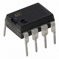
ST7FLITEUS5B6 STMicroelectronics, ST7FLITEUS5B6 Datasheet - Page 20

ST7FLITEUS5B6
Manufacturer Part Number
ST7FLITEUS5B6
Description
MCU 8BIT 1KB FLASH 128KB 8-DIP
Manufacturer
STMicroelectronics
Series
ST7r
Datasheet
1.STEVAL-IFS006V1.pdf
(136 pages)
Specifications of ST7FLITEUS5B6
Core Processor
ST7
Core Size
8-Bit
Speed
8MHz
Peripherals
LVD, POR, PWM, WDT
Number Of I /o
5
Program Memory Size
1KB (1K x 8)
Program Memory Type
FLASH
Ram Size
128 x 8
Voltage - Supply (vcc/vdd)
2.4 V ~ 5.5 V
Data Converters
A/D 5x10b
Oscillator Type
Internal
Operating Temperature
-40°C ~ 85°C
Package / Case
8-DIP (0.300", 7.62mm)
Controller Family/series
ST7
No. Of I/o's
5
Ram Memory Size
128Byte
Cpu Speed
8MHz
No. Of Timers
2
Rohs Compliant
Yes
For Use With
497-6403 - BOARD EVAL 8BIT MICRO + TDE1708497-6407 - BOARD EVAL FOR VACUUM CLEANER497-5861 - EVAL BRD POWER MOSFET/8PIN MCU497-5858 - EVAL BOARD PLAYBACK ST7FLITE497-5515 - EVAL BOARD PHASE CTRL DIMMER497-5049 - KIT STARTER RAISONANCE ST7FLITE497-5046 - KIT TOOL FOR ST7/UPSD/STR7 MCU
Lead Free Status / RoHS Status
Lead free / RoHS Compliant
Eeprom Size
-
Connectivity
-
Other names
497-5636-5
Available stocks
Company
Part Number
Manufacturer
Quantity
Price
Company:
Part Number:
ST7FLITEUS5B6
Manufacturer:
STMicroelectronics
Quantity:
8
Flash program memory
Caution:
4.5
4.5.1
20/136
Pin 9 has to be connected to the CLKIN pin of the ST7 when I
option bytes disabled (35-pulse I
I
selected in the option byte, the internal RC is provided. If AWU RC or external clock is
selected, the AWU RC oscillator is provided.
A serial resistor must be connected to I
PA3/RESET pin. Contention may occur if a tool forces a state on RESET pin while PA3 pin
forces the opposite state in output mode. The resistor value is defined to limit the current
below 2 mA at 5 V. If PA3 is used as output push-pull, then the application must be switched
off to allow the tool to take control of the RESET pin (PA3). To allow the programming tool to
drive the RESET pin below V
PA3 for application reasons.
During normal operation, ICCCLK pin must be pulled- up, internally or externally (external
pull-up of 10 kΩ mandatory in noisy environment). This is to avoid entering I
unexpectedly during a reset. In the application, even if the pin is configured as output, any
reset will put it back in input pull-up.
Figure 6.
Memory protection
There are two different types of memory protection: readout protection and Write/Erase
Protection which can be applied individually.
Readout protection
Readout protection, when selected provides a protection against program memory content
extraction and against write access to Flash memory. Even if no protection can be
considered as totally unbreakable, the feature provides a very high level of protection for a
general purpose microcontroller. Program memory is protected.
2
C entry mode), the internal RC clock (internal RC or AWU RC) is forced. If internal RC is
APPLICATION
POWER SUPPLY
Typical I
(See Note 3)
2
C interface
IL
, special care must also be taken when a pull-up is placed on
OPTIONAL
(See Note 4)
2
C entry mode). When option bytes are enabled (38-pulse
ST7
2
C connector pin 6 in order to prevent contention on
HE10 CONNECTOR TYPE
(See Note 5)
10
I
9
2
C CONNECTOR
PROGRAMMING TOOL
3.3kΩ
7
8
I
2
C CONNECTOR
5
6
4
3
I
2
C Cable
1
2
See Note 1 and Caution
See Note 1
2
C mode is selected with
ST7LITEUS2, ST7LITEUS5
APPLICATION BOARD
See Note 2
APPLICATION
RESET SOURCE
2
APPLICATION
C mode
I/O


