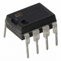
ST7FLITEUS5B6 STMicroelectronics, ST7FLITEUS5B6 Datasheet - Page 67

ST7FLITEUS5B6
Manufacturer Part Number
ST7FLITEUS5B6
Description
MCU 8BIT 1KB FLASH 128KB 8-DIP
Manufacturer
STMicroelectronics
Series
ST7r
Datasheet
1.STEVAL-IFS006V1.pdf
(136 pages)
Specifications of ST7FLITEUS5B6
Core Processor
ST7
Core Size
8-Bit
Speed
8MHz
Peripherals
LVD, POR, PWM, WDT
Number Of I /o
5
Program Memory Size
1KB (1K x 8)
Program Memory Type
FLASH
Ram Size
128 x 8
Voltage - Supply (vcc/vdd)
2.4 V ~ 5.5 V
Data Converters
A/D 5x10b
Oscillator Type
Internal
Operating Temperature
-40°C ~ 85°C
Package / Case
8-DIP (0.300", 7.62mm)
Controller Family/series
ST7
No. Of I/o's
5
Ram Memory Size
128Byte
Cpu Speed
8MHz
No. Of Timers
2
Rohs Compliant
Yes
For Use With
497-6403 - BOARD EVAL 8BIT MICRO + TDE1708497-6407 - BOARD EVAL FOR VACUUM CLEANER497-5861 - EVAL BRD POWER MOSFET/8PIN MCU497-5858 - EVAL BOARD PLAYBACK ST7FLITE497-5515 - EVAL BOARD PHASE CTRL DIMMER497-5049 - KIT STARTER RAISONANCE ST7FLITE497-5046 - KIT TOOL FOR ST7/UPSD/STR7 MCU
Lead Free Status / RoHS Status
Lead free / RoHS Compliant
Eeprom Size
-
Connectivity
-
Other names
497-5636-5
Available stocks
Company
Part Number
Manufacturer
Quantity
Price
Company:
Part Number:
ST7FLITEUS5B6
Manufacturer:
STMicroelectronics
Quantity:
8
ST7LITEUS2, ST7LITEUS5
Caution:
A watchdog reset can be forced at any time by setting the WDGRF bit. To generate a forced
watchdog reset, first watchdog has to be activated by setting the WDGE bit and then the
WDGRF bit has to be set.
The WDGRF bit also acts as a flag, indicating that the watchdog was the source of the reset.
It is automatically cleared after it has been read.
When the WDGRF bit is set, software must clear it, otherwise the next time the watchdog is
enabled (by hardware or software), the microcontroller will be immediately reset.
Hardware watchdog option
If hardware watchdog is selected by option byte, the watchdog is always active and the
WDGE bit in the LTCSR is not used.
Refer to the option byte description in the "device configuration and ordering information"
section.
Using Halt mode with the watchdog (option)
If the watchdog reset on Halt option is not selected by option byte, the Halt mode can be
used when the watchdog is enabled.
In this case, the HALT instruction stops the oscillator. When the oscillator is stopped, the Lite
Timer stops counting and is no longer able to generate a watchdog reset until the
microcontroller receives an external interrupt or a reset.
If an external interrupt is received, the WDG restarts counting after 256 or 512 CPU clocks.
If a reset is generated, the watchdog is disabled (reset state).
If Halt mode with watchdog is enabled by option byte (No watchdog reset on HALT
instruction), it is recommended before executing the HALT instruction to refresh the WDG
counter, to avoid an unexpected WDG reset immediately after waking up the microcontroller.
Figure 31. Watchdog timing diagram
Input capture
The 8-bit input capture register is used to latch the free-running upcounter after a rising or
falling edge is detected on the LTIC pin. When an input capture occurs, the ICF bit is set and
the LTICR register contains the MSB of the free-running upcounter. An interrupt is
generated if the ICIE bit is set. The ICF bit is cleared by reading the LTICR register.
The LTICR is a read only register and always contains the data from the last input capture.
Input capture is inhibited if the ICF bit is set.
WDGD BIT
INTERNAL
WATCHDOG
RESET
f
WDG
(2ms @ 8 MHz f
t
WDG
SOFTWARE SETS
OSC
WDGD BIT
)
HARDWARE CLEARS
WDGD BIT
WATCHDOG RESET
On-chip peripherals
67/136


