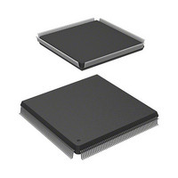
HD6417727F100C Renesas Electronics America, HD6417727F100C Datasheet - Page 199

HD6417727F100C
Manufacturer Part Number
HD6417727F100C
Description
IC SUPERH MPU ROMLESS 240QFP
Manufacturer
Renesas Electronics America
Series
SuperH® SH7700r
Datasheet
1.HD6417727BP100CV.pdf
(1098 pages)
Specifications of HD6417727F100C
Core Processor
SH-3 DSP
Core Size
32-Bit
Speed
100MHz
Connectivity
FIFO, SCI, SIO, SmartCard, USB
Peripherals
DMA, LCD, POR, WDT
Number Of I /o
104
Program Memory Type
ROMless
Ram Size
32K x 8
Voltage - Supply (vcc/vdd)
1.6 V ~ 2.05 V
Data Converters
A/D 6x10b; D/A 2x8b
Oscillator Type
Internal
Operating Temperature
-20°C ~ 75°C
Package / Case
240-QFP
Lead Free Status / RoHS Status
Contains lead / RoHS non-compliant
Eeprom Size
-
Program Memory Size
-
Available stocks
Company
Part Number
Manufacturer
Quantity
Price
Company:
Part Number:
HD6417727F100C
Manufacturer:
Renesas Electronics America
Quantity:
10 000
- Current page: 199 of 1098
- Download datasheet (7Mb)
• Manual Reset
• H-UDI Reset
Table 4.4
Type
Power-on
reset
Manual
reset
H-UDI
reset
4.5.2
• TLB miss exception
⎯ Conditions: RESETM low
⎯ Operations: EXPEVT set to H'020, VBR and SR initialized, branch to PC = H'A0000000.
⎯ Conditions: H-UDI reset command input (see section 31.4.3, H-UDI Reset)
⎯ Operations: EXPEVT set to H'000, VBR and SR initialized, branch to PC = H'A0000000.
⎯ Conditions: Comparison of TLB addresses shows no address match
⎯ Operations: The logical address (32 bits) that caused the exception is set in TEA and the
The PC and SR of the instruction that generated the exception are saved to the SPC and SSR,
respectively. If the exception occurred during a read, H'040 is set in EXPEVT; if the exception
occurred during a write, H'060 is set in EXPEVT. The BL, MD and RB bits in SR are set to 1
and a branch occurs to PC = VBR + H'0400.
Initialization sets the VBR register to H'00000000. In SR, the MD, RB, and BL bits are set
to 1 and the interrupt mask bits (I3 to I0) is set to 1111. The CPU and on-chip supporting
modules are initialized. See the register descriptions in the relevant sections for details. A
high level is output from the STATUS0 and STATUS1 pins.
Initialization sets the VBR register to H'0000000. In SR, the MD, RB and BL bits are set to
1 and the interrupt mask bits (I3 to I0) is set to 1111. The CPU and on-chip supporting
modules are initialized. See the register descriptions in the relevant sections for details.
corresponding virtual page number (22 bits) is set in PTEH (31 to 10). The ASID of PTEH
indicates the ASID at the time the exception occurred. The RC bit in MMUCR is
incremented by 1 when all ways are enabled, and if there is a disabled way, setting is
prioritized starting from way 0.
General Exceptions
Types of Reset
Conditions for Transition
to Reset State
RESETP = Low
RESETM = Low
H-UDI reset command input
CPU
Initialized
Initialized
Initialized
Rev.6.00 Mar. 27, 2009 Page 141 of 1036
On-Chip Supporting Modules
(See register configuration in
relevant sections)
Internal State
Section 4 Exception Handling
REJ09B0254-0600
Related parts for HD6417727F100C
Image
Part Number
Description
Manufacturer
Datasheet
Request
R

Part Number:
Description:
KIT STARTER FOR M16C/29
Manufacturer:
Renesas Electronics America
Datasheet:

Part Number:
Description:
KIT STARTER FOR R8C/2D
Manufacturer:
Renesas Electronics America
Datasheet:

Part Number:
Description:
R0K33062P STARTER KIT
Manufacturer:
Renesas Electronics America
Datasheet:

Part Number:
Description:
KIT STARTER FOR R8C/23 E8A
Manufacturer:
Renesas Electronics America
Datasheet:

Part Number:
Description:
KIT STARTER FOR R8C/25
Manufacturer:
Renesas Electronics America
Datasheet:

Part Number:
Description:
KIT STARTER H8S2456 SHARPE DSPLY
Manufacturer:
Renesas Electronics America
Datasheet:

Part Number:
Description:
KIT STARTER FOR R8C38C
Manufacturer:
Renesas Electronics America
Datasheet:

Part Number:
Description:
KIT STARTER FOR R8C35C
Manufacturer:
Renesas Electronics America
Datasheet:

Part Number:
Description:
KIT STARTER FOR R8CL3AC+LCD APPS
Manufacturer:
Renesas Electronics America
Datasheet:

Part Number:
Description:
KIT STARTER FOR RX610
Manufacturer:
Renesas Electronics America
Datasheet:

Part Number:
Description:
KIT STARTER FOR R32C/118
Manufacturer:
Renesas Electronics America
Datasheet:

Part Number:
Description:
KIT DEV RSK-R8C/26-29
Manufacturer:
Renesas Electronics America
Datasheet:

Part Number:
Description:
KIT STARTER FOR SH7124
Manufacturer:
Renesas Electronics America
Datasheet:

Part Number:
Description:
KIT STARTER FOR H8SX/1622
Manufacturer:
Renesas Electronics America
Datasheet:

Part Number:
Description:
KIT DEV FOR SH7203
Manufacturer:
Renesas Electronics America
Datasheet:


