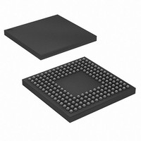
XR17V358IB176-F Exar Corporation, XR17V358IB176-F Datasheet - Page 5

XR17V358IB176-F
Manufacturer Part Number
XR17V358IB176-F
Description
IC UART PCIE OCTAL 176FPBGA
Manufacturer
Exar Corporation
Datasheet
1.XR17V358IB176-F.pdf
(68 pages)
Specifications of XR17V358IB176-F
Number Of Channels
1, UART
Package / Case
176-LFBGA
Features
*
Fifo's
256 Byte
Protocol
RS485
Voltage - Supply
1.2V, 3.3V
With Auto Flow Control
Yes
With Irda Encoder/decoder
Yes
With False Start Bit Detection
Yes
With Modem Control
Yes
Mounting Type
Surface Mount
Data Rate
25 Mbps
Supply Current
120 mA
Maximum Operating Temperature
+ 85 C
Minimum Operating Temperature
- 40 C
Mounting Style
SMD/SMT
Operating Supply Voltage
3.3 V
No. Of Channels
8
Uart Features
Tx/Rx FIFO Counters
Supply Voltage Range
3V To 3.6V
Operating Temperature Range
-40°C To +85°C
Digital Ic Case Style
BGA
No. Of Pins
176
Rohs Compliant
Yes
Lead Free Status / RoHS Status
Lead free / RoHS Compliant
For Use With
1016-1296 - EVAL BOARD FOR XR17V358-E81016-1295 - EVAL BOARD FOR XR17V358-E41016-1293 - EVAL BOARD FOR XR17V358
Lead Free Status / Rohs Status
Lead free / RoHS Compliant
Other names
1016-1294
Available stocks
Company
Part Number
Manufacturer
Quantity
Price
Company:
Part Number:
XR17V358IB176-F
Manufacturer:
EXAR
Quantity:
1 700
Company:
Part Number:
XR17V358IB176-F
Manufacturer:
Exar Corporation
Quantity:
10 000
Part Number:
XR17V358IB176-F
Manufacturer:
EXAR/艾科嘉
Quantity:
20 000
REV. 1.0.2
PIN DESCRIPTIONS
EXPANSION INTERFACE
CTS5#
DTR5#
DSR5#
CTS6#
DTR6#
DSR6#
CTS7#
DTR7#
DSR7#
RTS6#
RTS7#
MODE
CD5#
CD6#
CD7#
N
RI5#
RI6#
RI7#
RX6
RX7
CLK
TX6
TX7
AME
P
R10
P10
N10
P12
R13
M11
N12
G15
G14
P11
R11
N11
B3
B2
C3
B1
C2
R7
P8
P7
R9
P9
N9
IN
#
T
I/O
YPE
O
O
O
O
O
O
O
I
I
I
I
I
I
I
I
I
I
I
I
I
I
I
UART channel 5 Clear to Send or general purpose input (active LOW).
UART channel 5 Data Terminal Ready or general purpose output (active
LOW).
UART channel 5 Data Set Ready or general purpose input (active LOW).
UART channel 5 Carrier Detect or general purpose input (active LOW).
UART channel 5 Ring Indicator or general purpose input (active LOW).
UART channel 6 Transmit Data or infrared transmit data.
UART channel 6 Receive Data or infrared receive data. Normal RXD input
idles at HIGH condition. The infrared pulses can be inverted prior to decoding
by setting FCTR bit [4].
UART channel 6 Request to Send or general purpose output (active LOW).
UART channel 6 Clear to Send or general purpose input (active LOW).
UART channel 6 Data Terminal Ready or general purpose output (active
LOW).
UART channel 6 Data Set Ready or general purpose input (active LOW).
UART channel 6 Carrier Detect or general purpose input (active LOW).
UART channel 6 Ring Indicator or general purpose input (active LOW).
UART channel 7 Transmit Data or infrared transmit data.
UART channel 7 Receive Data or infrared receive data. Normal RXD input
idles at HIGH condition. The infrared pulses can be inverted prior to decoding
by setting FCTR bit [4].
UART channel 7 Request to Send or general purpose output (active LOW).
UART channel 7 Clear to Send or general purpose input (active LOW).
UART channel 7 Data Terminal Ready or general purpose output (active
LOW).
UART channel 7 Data Set Ready or general purpose input (active LOW).
UART channel 7 Carrier Detect or general purpose input (active LOW).
UART channel 7 Ring Indicator or general purpose input (active LOW).
Expansion Interface Mode Select. Connect this pin to VCC to enable master
mode or when there is no slave device. Connect this pin to GND when the
device is in slave mode.
Expansion Interface Clock. In master mode, this pin is the clock output to the
slave device. In slave mode, this pin is the clock input from the master
device. The expansion interface clock is 62.5MHz. The UARTs on the slave
device will need to use different baud rate generator divisors than the master
device. The trace capacitance between the master and slave device must be
less than 25pF.
HIGH PERFORMANCE OCTAL PCI EXPRESS UART
5
D
ESCRIPTION
XR17V358


