FS1A-C01S IDEC, FS1A-C01S Datasheet - Page 17
FS1A-C01S
Manufacturer Part Number
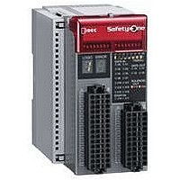
FS1A-C01S
Description
Safety Controller
Manufacturer
IDEC
Datasheet
1.FS1A-C01S.pdf
(48 pages)
Specifications of FS1A-C01S
No. Of Analog Outputs
11
No. Of Digital Inputs
30
Supply Voltage Dc, Min
20.4V
External Width
72mm
Supply Voltage Max
28.8VDC
External Depth
113.5mm
Supply Voltage Dc, Max
28.8V
Mounting Type
DIN Rail
Rohs Compliant
Yes
Approval Bodies
CULus, CE, TUV
External Height
114.5mm
Lead Free Status / RoHS Status
Lead free / RoHS Compliant


(09/01/07)
No programming required. Configuration completes by turning on a logic switch only.
•
•
•
•
•
•
Types
•
Input connector (FS9Z-CN01) ··················1 pc
Output connector (FS9Z-CN02) ···············1 pc
Marked cable tie (FS9Z-MT01)·················3 pcs
Setting tool ···············································1 pc
Instruction sheet (B-1088, English) ··········1 pc
Instruction sheet (B-1087, Japanese)·······1 pc
•
•
Specifications
•
Connector
Connecting Tool
Marked Cable Tie
DIN Rail
Mounting Clip
Safety Circuit
Operating Temperature –10 to +55°C (no freezing)
Operating Humidity
Storage Temperature
Storage Humidity
Pollution Degree
Degree of Protection
Corrosion Immunity
Altitude
Vibration Resistance
Shock Resistance
Connector Insertion/
Removal Durability
Configuration Switch
Durability
Enter Button Durability
Housing Material
Weight (approx.)
A safety circuit can be configured easily just by selecting a logic from
eight pre-programmed logics.
Partial/entire stop can be achieved just by selecting a logic.
One SafetyOne module can connect with various inputs such as
emergency stop switches and light curtains.
The status of safety I/Os and the SafetyOne errors can be monitored.
Solenoid drive output is provided, eliminating the need for PLC.
IEC 61508 integrity level 3, ISO 13849-1 performance level e,
and EN954-1 safety category 4 compliant
For details, see the user’s manual.
Standard Accessories
Optional Parts (sold separately)
Operating Environment
SafetyOne
Product
Product
For input
For output FS9Z-CN02
FS9Z-CN01
FS9Z-SD01
FS9Z-MT01PN10
BAA1000PN10
BNL6PN10
Logic selection type
10 to 95% RH (no condensation)
–40 to +70°C (no freezing)
10 to 95% RH (no condensation)
2 (IEC/EN60664-1)
IP20 (IEC/EN60529)
Free from corrosive gases
Operation: 0 to 2000m, Transport: 0 to 3000m
Vibration:
Acceleration: 9.8 m/s
mutually perpendicular axes)
(IEC/EN61131-2)
Bump: Acceleration 98 m/s
each on three mutually perpendicular axes)
(IEC/EN61496-1)
147 m/s
perpendicular axes (IEC/EN 61131-2)
50 times maximum
100 operations maximum per pole
1000 operations maximum
Modified-polyphenyleneether (m-PPE)
330g
Ordering Type No.
2
, 11ms (3 shocks each on three mutually
Ordering Type No.
5 to 8.4 Hz, amplitude 3.5 mm
8.4 to 150 Hz
FS1A-C01S
Package
2
Quantity
(2 hours each on three
10
10
10
1
1
1
FS1A
2
, 16 ms (1000 times
Used to lock the
protection cover
of the FS1A.
Aluminum, 1m
35mm wide
Note
•
Note 1: The time to shut off safety outputs after inputs are turned off or input
Note 2: Time to shut off safety outputs after an error (except input monitor
Note 3: Auto start—Time to turn on safety outputs after safe inputs are
Note 4: Time to transit to Run state after power supply is turned on.
TÜV approval:
IEC/EN 61000-6-2, IEC/EN 61000-6-4, IEC/EN 61496-1, IEC 61508 Part1-7,
IEC/EN 62061, ISO 13849-1, EN 954-1
UL:
UL508, CSA C22.2 No. 142
Applicable standards:
IEC/EN 60204-1, IEC/EN 61131-2, ISO 10218-1, ANSI/RIA R15.06, ANSI
B11.19, SEMI S2-0706, NFPA79
Safety Controller
Rated Voltage
Allowable Voltage Range 20.4 to 28.8V DC
Maximum Power
Consumption
Allowable Momentary
Power Interruption
Response Time
Start-up Time (Note 4)
Dielectric Strength
Insulation Resistance
Impulse Noise Immunity
(noise simulator)
Inrush Current
Ground
Effect of Incorrect
Wiring
Electric Characteristics
monitor error is detected (when off-delay timer is set to 0s)
error) or a configuration change of logic or timer is detected (not
depending on the off-delay timer value)
turned on
Manual start—Time to turn on safety outputs after start inputs are
turned on
Control start—Time to turn on safety outputs after the start inputs
are turned off-on-off (maintain ON for 0.1 to 5s)
24V DC
48W (at the rated power voltage, when all I/Os
are ON) (incl. output load)
10 ms minimum (at the rated power voltage)
ON–OFF: 40 ms maximum (Note 1)/
OFF–ON: 100 ms maximum (Note 3)
6s maximum
Between live part and FE terminal:
Between housing and FE terminal:
Between live part and FE terminal:
Between housing and FE terminal:
Power terminal: ±1 kV 50ns, 1μs
I/O terminal: ±1kV 50ns, 1μs (coupling adapter)
25A maximum
Ground resistance of 100Ω or less
Reverse polarity: No operation, no damage
Improper voltage: Permanent damage may oc-
cur
500V AC, 1 minute
500V AC, 1 minute
10 MΩ minimum (500V DC megger)
10 MΩ minimum (500V DC megger)
100 ms maximum (Note 2)
(direct connection)
17
Related parts for FS1A-C01S
Image
Part Number
Description
Manufacturer
Datasheet
Request
R

Part Number:
Description:
Safety Controller
Manufacturer:
IDEC
Datasheet:

Part Number:
Description:
Cable; Between IDEC MicroSmart (port 1 or 2) and HG2F/3F/4F; 5 ft.
Manufacturer:
IDEC Corporation
Datasheet:
Part Number:
Description:
Cable; Between IDEC Micro^3C/ONC/MicroSmart (port 2) PLCs and HG2F/3F/4F; 5 ft.
Manufacturer:
IDEC Corporation
Datasheet:
Part Number:
Description:
Angled Key for Idec HS6B Safety Switch
Manufacturer:
IDEC Corporation
Datasheet:
Part Number:
Description:
Accessory, L-Shaped Key for Idec HS5B and HS5E Safety Switch
Manufacturer:
IDEC Corporation
Datasheet:
Part Number:
Description:
Accessory, Straight Key for Idec HS5B and HS5E Safety Switch
Manufacturer:
IDEC Corporation
Datasheet:
Part Number:
Description:
Straight Key for Idec HS6B Safety Switch
Manufacturer:
IDEC Corporation
Datasheet:
Part Number:
Description:
LIGHT TOWER 3 TIER RED/AMBER/GREEN 24VAC/DC WALL MOUNT
Manufacturer:
IDEC Corporation
Datasheet:
Part Number:
Description:
Flat Lens, 24V AC/DC, 1m Cable Length, Alternate: Red Green Color, IP67
Manufacturer:
IDEC Corporation
Datasheet:
Part Number:
Description:
LIGHT TOWER 2 TIER RED/GREEN 24VAC/DC WALL MOUNT
Manufacturer:
IDEC Corporation
Datasheet:
Part Number:
Description:
INDICATOR INCANDESCENT LAMP, GREEN
Manufacturer:
IDEC
Datasheet:

Part Number:
Description:
LAMP, INDICATOR, INCAND, AMB
Manufacturer:
IDEC
Datasheet:
Part Number:
Description:
LAMP, INDICATOR, INCAND, GRN
Manufacturer:
IDEC
Datasheet:
Part Number:
Description:
LAMP, INDICATOR, INCAND, GRN
Manufacturer:
IDEC
Datasheet:
Part Number:
Description:
LAMP, INDICATOR, INCANDESCENT, RED
Manufacturer:
IDEC
Datasheet: