FS1A-C01S IDEC, FS1A-C01S Datasheet - Page 19
FS1A-C01S
Manufacturer Part Number
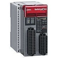
FS1A-C01S
Description
Safety Controller
Manufacturer
IDEC
Datasheet
1.FS1A-C01S.pdf
(48 pages)
Specifications of FS1A-C01S
No. Of Analog Outputs
11
No. Of Digital Inputs
30
Supply Voltage Dc, Min
20.4V
External Width
72mm
Supply Voltage Max
28.8VDC
External Depth
113.5mm
Supply Voltage Dc, Max
28.8V
Mounting Type
DIN Rail
Rohs Compliant
Yes
Approval Bodies
CULus, CE, TUV
External Height
114.5mm
Lead Free Status / RoHS Status
Lead free / RoHS Compliant


(09/01/07)
Solenoid/Lamp Output Specifications
The selected operating characteristics of solenoid/lamp output change
depending on the selected logic. For details, see user’s manual “Chapter 5
Logic.” The basic specifications remain the same. Do not use solenoid/lamp
output as safety output, otherwise the system’s safety cannot be assured
when the SafetyOne or safety components fail.
Internal States
LED and Output Status
Note 1: Random display of Initial state.
Note 2: Output and LED display of the selected logic.
Note 3: Blinking LED display of the selected logic number or the selected
Note 4: Pulsing display of monitor output and output LED corresponding
Note 5: Error number is displayed.
Caution
Solenoid/lamp outputs (Y17, Y20) turn on for 1 second maximum when the
state shifts to Run state. Take the operation of the connected components
into consideration.
Note 1: When connecting an inductive load, connect a protection element
Note 2: When the wiring between the SafetyOne and the connected compo-
• Solenoid/Lamp Ouput Internal Circuit
Initial
Run
Configura-
tion
Protection Logic #
Stop
Output Type
Rated Output Voltage
Minimum Output Voltage
No. of Solenoid/Lamp Outputs 2 (Y17, Y20)
Maximum
Output Current
Leakage Current
Allowable Inductive Load
(Note 1)
Cable Length (Note 2)
Initial
Run
Configuration
Protection
Stop
Internal
Circuit
State
State
such as a diode.
nent is 30m or more, use a shielded cable to ensure electromagnetic
immunity.
timer value.
to the input of error. Other LEDs and monitor outputs maintain the
display of Run state.
(Note 1) (Note 1) (Note 1)
(Note 3)
Logic #
Logic
Blank
LED
Initial processing is performed immediately after power
is supplied to the SafetyOne. The internal circuits are
checked and the LEDs show operation confirmation (blink-
ing) for 6 seconds (approx).
The SafetyOne is under normal operation. Logic process-
ing continues without failures or wiring errors.
A logic or off-delay timer value is being configured.
Configuration enables the logic and off-delay timer value.
When completed, the SafetyOne shifts to the Run state.
An input monitor error has occurred with dual channel
input, EDM input, or muting input. When the problem is
removed, the SafetyOne shifts to Run state.
A failure or error has occurred with an external device
or internal circuit. When the problem is removed and the
power is turned on, Stop state is cleared.
1 output
Total
(Note 5)
Error
Blank
LED
V+
C
1
(Note 3)
Circuit
Logic
Timer
Value
Value
Blank
LED
Source output (N channel MOSFET)
Power supply voltage
Power supply voltage – 2.0V
500 mA maximum
500 mA maximum
0.1 mA maximum
L/R = 25 ms
100m maximum (total length per output)
Y0 to Y3 Y17, Y20
(Note 2)
Output
Safety
OFF
OFF
OFF
OFF
Description
Solenoid/
(Note 2)
Output
Lamp
OFF
OFF
OFF
OFF
Y17, Y20
V–
(Note 2)
(Note 4)
Y4 to
OFF
OFF
OFF
Y13
Monitor Output
OFF
OFF
OFF
Y14
ON
ON
ON or
OFF
OFF
Y15
ON
ON
ON
OFF
OFF
OFF
OFF
Y16
ON
LEDs
•
•
Note: Blinks for 1 to 5 seconds after the enter button is pressed. Releasing the
button during blinking activates the setting. The blinking LED becomes ON if the
button is pressed for more than 5 seconds, and the setting becomes invalid even
after the button is released.
•
•
•
Random ON/Blink Initializing (Initial state)
Y17, Y20
X0 to X15
Y0 to Y3
All LEDs
X16, X17
Random ON/Blink Initializing (Initial state)
Random
Logic LED
Error LED
Timer LED
Output LED
SAFE-OUT (Y0 to Y3), SOLENOID-OUT (Y17, Y20)
Input LED
SAFE-IN (X0 to X15), START-IN (X16, X17)
LED
OFF
LED
1 to 8
LED
Each
LED
OFF
LED
C
LED
1
2
3
4
5
6
7
9
15
30
.1
.5
E
0
1
2
5
Status
� �
Blink
ON/Blink Initializing (Initial state)
OFF
Status
Status
ON
ON
ON
ON
ON
ON
ON
ON
ON
Status
Blink
Blink
OFF
Blink
Status
OFF
Blink
ON
OFF
OFF
ON
ON
ON
ON
ON
ON
ON
ON
Blink
OFF
OFF
ON
ON
ON
ON
�
Input monitor error (Protection state)
Wiring error at safety input or an error in safety input
circuits
Wiring error at start input or an error in start input circuit
Wiring error at safety output or an error in safety output
circuit
Muting lamp error (disconnection) (Logic 4 only)
Power supply error or internal power supply circuit error
Internal error, power supply error, or internal power
supply circuit error
EMC disturbance
Configuration procedure is in progress (Configuration
state)
Configuration is valid (Note) (Configuration state)
Normal operation (Run state)
The selected logic is in Run or Protection state
The selected logic is in Configuration state
The selected logic has Configuration error (logic not
selected, or more than one logics are selected)
Error (Stop state)
No off-delay (safety outputs shut down immediately)
Off-delay timer 0.1s
Off-delay timer 0.5s
Off-delay timer 1s
Off-delay timer 2s
Off-delay timer 5s
Off-delay timer 15s
Off-delay timer 30s
Selected timer value (Configuration state)
Timer value is not selected or the SafetyOne is in
Stop state
FS1A Safety Controller
�
Input ON
Input OFF, Stop/Configuration state
Input monitor error
Input ON
Input OFF, Stop/Configuration state
Output ON
Output OFF, Stop/Configuration state
Off-delay operating
Output ON
Output OFF, Stop/Configuration state
Description
Description
� Logic LED (green)
� Error LED (red)
� Timer LED (green)
� Input/Output LED (orange)
–SAFE-IN
–START-IN
–SAFE-OUT
–SOLENOID-OUT
Description
Description
Description
19
Related parts for FS1A-C01S
Image
Part Number
Description
Manufacturer
Datasheet
Request
R

Part Number:
Description:
Safety Controller
Manufacturer:
IDEC
Datasheet:

Part Number:
Description:
Cable; Between IDEC MicroSmart (port 1 or 2) and HG2F/3F/4F; 5 ft.
Manufacturer:
IDEC Corporation
Datasheet:
Part Number:
Description:
Cable; Between IDEC Micro^3C/ONC/MicroSmart (port 2) PLCs and HG2F/3F/4F; 5 ft.
Manufacturer:
IDEC Corporation
Datasheet:
Part Number:
Description:
Angled Key for Idec HS6B Safety Switch
Manufacturer:
IDEC Corporation
Datasheet:
Part Number:
Description:
Accessory, L-Shaped Key for Idec HS5B and HS5E Safety Switch
Manufacturer:
IDEC Corporation
Datasheet:
Part Number:
Description:
Accessory, Straight Key for Idec HS5B and HS5E Safety Switch
Manufacturer:
IDEC Corporation
Datasheet:
Part Number:
Description:
Straight Key for Idec HS6B Safety Switch
Manufacturer:
IDEC Corporation
Datasheet:
Part Number:
Description:
LIGHT TOWER 3 TIER RED/AMBER/GREEN 24VAC/DC WALL MOUNT
Manufacturer:
IDEC Corporation
Datasheet:
Part Number:
Description:
Flat Lens, 24V AC/DC, 1m Cable Length, Alternate: Red Green Color, IP67
Manufacturer:
IDEC Corporation
Datasheet:
Part Number:
Description:
LIGHT TOWER 2 TIER RED/GREEN 24VAC/DC WALL MOUNT
Manufacturer:
IDEC Corporation
Datasheet:
Part Number:
Description:
INDICATOR INCANDESCENT LAMP, GREEN
Manufacturer:
IDEC
Datasheet:

Part Number:
Description:
LAMP, INDICATOR, INCAND, AMB
Manufacturer:
IDEC
Datasheet:
Part Number:
Description:
LAMP, INDICATOR, INCAND, GRN
Manufacturer:
IDEC
Datasheet:
Part Number:
Description:
LAMP, INDICATOR, INCAND, GRN
Manufacturer:
IDEC
Datasheet:
Part Number:
Description:
LAMP, INDICATOR, INCANDESCENT, RED
Manufacturer:
IDEC
Datasheet: