FS1A-C01S IDEC, FS1A-C01S Datasheet - Page 46
FS1A-C01S
Manufacturer Part Number
FS1A-C01S
Description
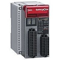
Safety Controller
Manufacturer
IDEC
Datasheet
1.FS1A-C01S.pdf
(48 pages)
Specifications of FS1A-C01S
No. Of Analog Outputs
11
No. Of Digital Inputs
30
Supply Voltage Dc, Min
20.4V
External Width
72mm
Supply Voltage Max
28.8VDC
External Depth
113.5mm
Supply Voltage Dc, Max
28.8V
Mounting Type
DIN Rail
Rohs Compliant
Yes
Approval Bodies
CULus, CE, TUV
External Height
114.5mm
Lead Free Status / RoHS Status
Lead free / RoHS Compliant


Dimensions
Installation Location
When installing the SafetyOne in an enclosure such as a control
panel, make sure that the operating condition satisfies the specifi-
cations of the SafetyOne. Do not use the SafetyOne in an environ-
ment described below, or where the operating conditions exceed
the limit of the SafetyOne. Otherwise electric shock, fire hazard,
damage, or malfunction will be caused.
•
•
•
For maintenance and ventilation, provide space around the Safety-
One as shown in the figure below, so that sufficient distance is kept
from other components, heat source, or panel surface.
Direction
Install the SafetyOne vertically as shown in Figure 1. Do not install
in other directions (Figure 2).
46
Near inductive device or heat source
Where excessive dust, dirt, salt, or iron powder is present
Where the SafetyOne is exposed to vibration or shock
Operating Instructions
40 mm
min.
Locking Hole Dimensions
Figure 1. Correct Mounting Direction
20 mm min.
20 mm min.
1.7
40 mm
min.
80 mm min.
Panel
Duct
End Clip
BNL6
FS1A
20 mm min.
20 mm min.
Series
Safety Controller
Installing on DIN Rails
Use 35mm-wide DIN rails for installing the SafetyOne.
Applicable DIN rails: BAA1000 (IDEC)
Installing
1. Fasten the DIN rail to a panel using screws firmly.
2. Pull out the clamp from the SafetyOne module, and put the
3. Use BNL6 end clips on both sides of the SafetyOne module to
Removal
1. Insert the tip of a flat screwdriver into the latch.
2. Pull down the latch until the latch clicks.
3. Pull out the SafetyOne lightly, and remove from the DIN rail.
Locking
Hole
groove of the module on the DIN rail. Press the module towards
the DIN rail and push in the clamp as shown below.
prevent from moving sideways.
Upward
Installing
Figure 2. Incorrect Mounting Directions
35-mm-wide
DIN Rail
Sideways
72.0
All dimensions in mm.
Removing
Downward
35-mm-wide
DIN Rail
Clamp
(09/01/07)
Related parts for FS1A-C01S
Image
Part Number
Description
Manufacturer
Datasheet
Request
R

Part Number:
Description:
Safety Controller
Manufacturer:
IDEC
Datasheet:

Part Number:
Description:
Cable; Between IDEC MicroSmart (port 1 or 2) and HG2F/3F/4F; 5 ft.
Manufacturer:
IDEC Corporation
Datasheet:
Part Number:
Description:
Cable; Between IDEC Micro^3C/ONC/MicroSmart (port 2) PLCs and HG2F/3F/4F; 5 ft.
Manufacturer:
IDEC Corporation
Datasheet:
Part Number:
Description:
Angled Key for Idec HS6B Safety Switch
Manufacturer:
IDEC Corporation
Datasheet:
Part Number:
Description:
Accessory, L-Shaped Key for Idec HS5B and HS5E Safety Switch
Manufacturer:
IDEC Corporation
Datasheet:
Part Number:
Description:
Accessory, Straight Key for Idec HS5B and HS5E Safety Switch
Manufacturer:
IDEC Corporation
Datasheet:
Part Number:
Description:
Straight Key for Idec HS6B Safety Switch
Manufacturer:
IDEC Corporation
Datasheet:
Part Number:
Description:
LIGHT TOWER 3 TIER RED/AMBER/GREEN 24VAC/DC WALL MOUNT
Manufacturer:
IDEC Corporation
Datasheet:
Part Number:
Description:
Flat Lens, 24V AC/DC, 1m Cable Length, Alternate: Red Green Color, IP67
Manufacturer:
IDEC Corporation
Datasheet:
Part Number:
Description:
LIGHT TOWER 2 TIER RED/GREEN 24VAC/DC WALL MOUNT
Manufacturer:
IDEC Corporation
Datasheet:
Part Number:
Description:
INDICATOR INCANDESCENT LAMP, GREEN
Manufacturer:
IDEC
Datasheet:

Part Number:
Description:
LAMP, INDICATOR, INCAND, AMB
Manufacturer:
IDEC
Datasheet:
Part Number:
Description:
LAMP, INDICATOR, INCAND, GRN
Manufacturer:
IDEC
Datasheet:
Part Number:
Description:
LAMP, INDICATOR, INCAND, GRN
Manufacturer:
IDEC
Datasheet:
Part Number:
Description:
LAMP, INDICATOR, INCANDESCENT, RED
Manufacturer:
IDEC
Datasheet: