FS1A-C01S IDEC, FS1A-C01S Datasheet - Page 18
FS1A-C01S
Manufacturer Part Number
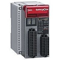
FS1A-C01S
Description
Safety Controller
Manufacturer
IDEC
Datasheet
1.FS1A-C01S.pdf
(48 pages)
Specifications of FS1A-C01S
No. Of Analog Outputs
11
No. Of Digital Inputs
30
Supply Voltage Dc, Min
20.4V
External Width
72mm
Supply Voltage Max
28.8VDC
External Depth
113.5mm
Supply Voltage Dc, Max
28.8V
Mounting Type
DIN Rail
Rohs Compliant
Yes
Approval Bodies
CULus, CE, TUV
External Height
114.5mm
Lead Free Status / RoHS Status
Lead free / RoHS Compliant


Safety Input Specifications
•
Note: Drive terminals of safety inputs send safety confirmation signals (pulse
•
•
Note: When the wiring between the SafetyOne and the connected compo-
• Receive Terminal
Xn
Start Input Specifications
Note: When the wiring between the SafetyOne and the connected compo-
X16, X17
18
•
Rated Drive Voltage
Minimum Drive Voltage
Number of Drive Terminals 14
Maximum Drive Current
Rated Input Voltage 24V DC
Input ON Voltage
Input OFF Voltage
Number of Inputs
Input Current
Input Signal
Cable Length (Note) 100m maximum (total wire length per input)
Allowable Wire
Resistance
Rated Input Voltage
Input ON Voltage
Input OFF Voltage
Number of Start Inputs 2 (X16, X17)
Input Current
Input Signal
Cable Length (Note)
Allowable Wire
Resistance
Internal Circuit
Start Input Internal Circuit
Drive Terminals
(T0, T1, T2, T3, T4, T5, T6, T7, T10, T11, T12, T13, T14, T15)
Receive Terminals
(X0, X1, X2, X3, X4, X5, X6, X7, X10, X11, X12, X13, X14, X15)
Wire
nent is 30m or more, use a shielded cable to ensure electromagnetic
immunity.
nent is 30m or more, use a shielded cable to ensure electromagnetic
immunity.
signals) for the diagnosis of safety components and input circuits.
(Wiring and diagnosis function change depending on the selected
logic. See user’s manual “Chapter 5 Logic.” Basic specifications
remain the same.
2.2 kΩ
4.7 k
V–
15.0 to 28.8V DC
Open or 0 to 5.0V DC
14
10 mA per terminal (at the rated power voltage)
Sink input (for PNP output), Type 1 (IEC61131-2)
300Ω maximum
V–
24V DC
15.0 to 28.8V DC
Open or 0V to 5.0V DC
5 mA per terminal (at the rated power voltage)
Sink input (PNP output), Type 1 (IEC61131-2)
100m maximum (total wire length per input)
300Ω maximum
Power supply voltage
Power supply voltage – 2.0V
20 mA per terminal (28.8V DC) (Note)
• Receive Terminal
Voltage (V)
28.8
•
Voltage (V)
Operating Range
24
15
5
Start Input Operation Range
28.8
24
15
5
1
OFF Range
FS1A Safety Controller
0.5
OFF Range
6
Transition
ON Range
Range
3
Transition
ON Range
Range
10
5
12
6
Current
(mA)
Current
(mA)
Safety Output Specifications
Monitor Output Specifications
Note: When the wiring between the SafetyOne and the connected compo-
• Monitor Output Internal Circuit
Note 1: When connecting an inductive load, connect a protection element
Note 2: When the wiring between the SafetyOne and the connected compo-
• Safety Output Internal Circuit
The safety outputs of the SafetyOne are solid state outputs. When the out-
put is on, off-check signals are generated at regular intervals. The operating
characteristics of the safety output change depending on the selected logic.
For details, see user’s manual “Chapter 5 Logic.” The basic specifications
remain the same.
Note that off-check signals may cause reaction of some safety components
depending on their response speed.
Monitor output and solenoid/lamp output do not generate outputs of off-
check signals.
The operating characteristics of the monitor output change depending on
the selected logic. For details, see user’s manual “Chapter 5 Logic.” The
basic specifications remain the same.
Do not use monitor output as safety output, otherwise the system’s safety
cannot be assured when the SafetyOne or safety components fail.
Output Type
Rated Output Voltage
Minimum Output Voltage
Number of Safety Outputs
Maximum
Output Current
Leakage Current
Allowable Inductive Load
(Note 1)
Allowable Capacitive Load
Cable Length (Note 2)
Output Type
Rated Output Voltage
Minimum Output Voltage Power supply voltage – 2.0V
Number of Monitor
Outputs
Maximum
Output Current
Leakage Current
Cable Length (Note)
OFF
nent is 30m or more, use a shielded cable to ensure electromagnetic
immunity.
ON
such as a diode.
nent is 30m or more, use a shielded cable to ensure electromagnetic
immunity.
Internal
Circuit
Internal
Circuit
1 output
Total
1 output 20 mA maximum
Total
Approx. 40 ms
Off cycle:
Off time: Approx. 400 µs
V+
V+
Source output (N channel MOSFET)
Power supply voltage
11 (Y4, Y5, Y6, Y7, Y10, Y11, Y12, Y13, Y14,
Y15, Y16)
220 mA maximum
0.1 mA maximum
100m maximum (total length per output)
Source output (N channel MOSFET)
Power supply voltage
Power supply voltage – 2.0V
4 (Y0, Y1, Y2, Y3)
500 mA maximum
1A maximum
0.1 mA maximum
L/R = 25 ms
1 μF maximum
100m maximum (total length per output)
Circuit
Logic
Circuit
Logic
Y0 to Y3
V–
Yn
V–
(09/01/07)
Related parts for FS1A-C01S
Image
Part Number
Description
Manufacturer
Datasheet
Request
R

Part Number:
Description:
Safety Controller
Manufacturer:
IDEC
Datasheet:

Part Number:
Description:
Cable; Between IDEC MicroSmart (port 1 or 2) and HG2F/3F/4F; 5 ft.
Manufacturer:
IDEC Corporation
Datasheet:
Part Number:
Description:
Cable; Between IDEC Micro^3C/ONC/MicroSmart (port 2) PLCs and HG2F/3F/4F; 5 ft.
Manufacturer:
IDEC Corporation
Datasheet:
Part Number:
Description:
Angled Key for Idec HS6B Safety Switch
Manufacturer:
IDEC Corporation
Datasheet:
Part Number:
Description:
Accessory, L-Shaped Key for Idec HS5B and HS5E Safety Switch
Manufacturer:
IDEC Corporation
Datasheet:
Part Number:
Description:
Accessory, Straight Key for Idec HS5B and HS5E Safety Switch
Manufacturer:
IDEC Corporation
Datasheet:
Part Number:
Description:
Straight Key for Idec HS6B Safety Switch
Manufacturer:
IDEC Corporation
Datasheet:
Part Number:
Description:
LIGHT TOWER 3 TIER RED/AMBER/GREEN 24VAC/DC WALL MOUNT
Manufacturer:
IDEC Corporation
Datasheet:
Part Number:
Description:
Flat Lens, 24V AC/DC, 1m Cable Length, Alternate: Red Green Color, IP67
Manufacturer:
IDEC Corporation
Datasheet:
Part Number:
Description:
LIGHT TOWER 2 TIER RED/GREEN 24VAC/DC WALL MOUNT
Manufacturer:
IDEC Corporation
Datasheet:
Part Number:
Description:
INDICATOR INCANDESCENT LAMP, GREEN
Manufacturer:
IDEC
Datasheet:

Part Number:
Description:
LAMP, INDICATOR, INCAND, AMB
Manufacturer:
IDEC
Datasheet:
Part Number:
Description:
LAMP, INDICATOR, INCAND, GRN
Manufacturer:
IDEC
Datasheet:
Part Number:
Description:
LAMP, INDICATOR, INCAND, GRN
Manufacturer:
IDEC
Datasheet:
Part Number:
Description:
LAMP, INDICATOR, INCANDESCENT, RED
Manufacturer:
IDEC
Datasheet: