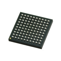
KSZ8893MBLI Micrel Inc, KSZ8893MBLI Datasheet - Page 29

KSZ8893MBLI
Manufacturer Part Number
KSZ8893MBLI
Description
2+1 Port 10/100 Switch W/ Tranceivers & Frame Buffers ( )
Manufacturer
Micrel Inc
Datasheet
1.KSZ8893MBLI.pdf
(116 pages)
Specifications of KSZ8893MBLI
Controller Type
Ethernet Switch Controller
Interface
MII, RMII, SNI
Voltage - Supply
3.1 V ~ 3.5 V
Operating Temperature
-40°C ~ 85°C
Mounting Type
Surface Mount
Package / Case
100-LFBGA
Number Of Primary Switch Ports
3
Operating Supply Voltage (typ)
3.3V
Fiber Support
Yes
Integrated Led Drivers
Yes
Power Supply Type
Analog/Digital
Data Rate (typ)
10/100Mbps
Vlan Support
Yes
Operating Temperature (max)
85C
Operating Temperature (min)
-40C
Mounting
Surface Mount
Jtag Support
No
Operating Supply Voltage (max)
3.5V
Operating Supply Voltage (min)
3.1V
Operating Temperature Classification
Industrial
Data Rate
100Mbps
Lead Free Status / RoHS Status
Lead free / RoHS Compliant
Current - Supply
-
Lead Free Status / RoHS Status
Not Compliant, Lead free / RoHS Compliant
Other names
576-3575
Available stocks
Company
Part Number
Manufacturer
Quantity
Price
Company:
Part Number:
KSZ8893MBLI
Manufacturer:
Micrel
Quantity:
2 022
Scrambler/De-scrambler (100BASE-TX Only)
The purpose of the scrambler is to spread the power spectrum of the signal to reduce electromagnetic
interference (EMI) and baseline wander. Transmitted data is scrambled through the use of an 11-bit wide linear
feedback shift register (LFSR). The scrambler generates a 2047-bit non-repetitive sequence, and the receiver
then de-scrambles the incoming data stream using the same sequence as at the transmitter.
100BASE-FX Operation
100BASE-FX operation is similar to 100BASE-TX operation with the differences being that the scrambler/de-
scrambler and MLT3 encoder/decoder are bypassed on transmission and reception. In addition, auto-negotiation
is bypassed and auto MDI/MDI-X is disabled.
100BASE-FX Signal Detection
In 100BASE-FX operation, FXSD1 (fiber signal detect), input pin 44, is usually connected to the fiber transceiver
SD (signal detect) output pin. 100BASE-FX mode is activated when the FXSD1 input pin is greater than 1V.
When FXSD1 is between 1V and 1.8V, no fiber signal is detected and a far-end fault (FEF) is generated. When
FXSD1 is over 2.2V, the fiber signal is detected.
Alternatively, the designer may choose not to implement the FEF feature. In this case, the FXSD1 input pin is tied
high to force 100BASE-FX mode.
100BASE-FX signal detection is summarized in the following table:
To ensure proper operation, a resistive voltage divider is recommended to adjust the fiber transceiver SD output
voltage swing to match the FXSD1 pin’s input voltage threshold.
100BASE-FX Far-End Fault
A far-end fault (FEF) occurs when the signal detection is logically false on the receive side of the fiber transceiver.
The KSZ8893MQL/MBL detects a FEF when its FXSD1 input is between 1V and 1.8V. When a FEF is detected,
the KSZ8893MQL/MBL signals its fiber link partner that a FEF has occurred by sending 84 1’s followed by a zero
in the idle period between frames.
By default, FEF is enabled. FEF can be disabled through register setting.
10BASE-T Transmit
The 10BASE-T driver is incorporated with the 100BASE-TX driver to allow for transmission using the same
magnetics. They are internally wave-shaped and pre-emphasized into outputs with a typical 2.3V amplitude. The
harmonic contents are at least 27dB below the fundamental frequency when driven by an all-ones Manchester-
encoded signal.
February 2010
FXSD1 Input Voltage
Less than 0.2V
Greater than 1V, but less than 1.8V
Greater than 2.2V
Table 1. FX and TX Mode Selection
29
Mode
TX mode
FX mode
No signal detected.
Far-end fault generated
FX mode
Signal detected
M9999-021110-1.6


