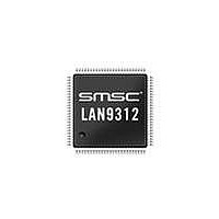
LAN9312-NZW SMSC, LAN9312-NZW Datasheet - Page 167

LAN9312-NZW
Manufacturer Part Number
LAN9312-NZW
Description
Ethernet ICs Hi Per 2 Port 10/100 Ethernet Switch
Manufacturer
SMSC
Type
Two Port Managed Ethernet Switchr
Datasheet
1.LAN9312-NZW.pdf
(458 pages)
Specifications of LAN9312-NZW
Ethernet Connection Type
10 Base-T, 100 Base-TX
Minimum Operating Temperature
0 C
Mounting Style
SMD/SMT
Product
Ethernet Switches
Number Of Transceivers
1
Standard Supported
802.3, 802.3u
Data Rate
10 Mbps, 100 Mbps
Supply Voltage (max)
3.3 V
Supply Voltage (min)
0 V
Supply Current (max)
186 mA, 295 mA
Maximum Operating Temperature
+ 70 C
Package / Case
TQFP-100
Lead Free Status / RoHS Status
Lead free / RoHS Compliant
Available stocks
Company
Part Number
Manufacturer
Quantity
Price
Company:
Part Number:
LAN9312-NZW
Manufacturer:
Standard
Quantity:
143
Company:
Part Number:
LAN9312-NZW
Manufacturer:
Microchip Technology
Quantity:
10 000
- Current page: 167 of 458
- Download datasheet (5Mb)
High Performance Two Port 10/100 Managed Ethernet Switch with 32-Bit Non-PCI CPU Interface
Datasheet
SMSC LAN9312
14.1
14.1.1
14.1.2
14.1.3
The LAN9312 contains four host-accessible FIFO’s: TX Status, RX Status, TX Data, and RX Data.
These FIFO’s store the incoming and outgoing address and data information, acting as a conduit
between the host bus interface (HBI) and the Host MAC. The sizes of these FIFO’s are configurable
via the
Configuration," on page 121
For additional information on the FIFO configuration registers accessible via the Host Bus Interface,
refer to their respective register definitions located in section
TX/RX Data FIFO’s
The TX and RX Data FIFO ports have the base address of 020h and 000h respectively. However, each
FIFO is also accessible at seven additional contiguous memory locations, as can be seen in
Figure
they all function identically and contain the same data. This alias port addressing is implemented to
allow hosts to burst through sequential addresses.
TX/RX Status FIFO’s
The TX and RX Status FIFO’s can each be read from two register locations; the Status FIFO Port, and
the Status FIFO PEEK. The TX and RX Status FIFO Ports (048h and 040h respectively) will perform
a destructive read, popping the data from the TX or RX Status FIFO. The TX and RX Status FIFO
PEEK register locations (04Ch and 044h respectively) allow a non-destructive read of the top (oldest)
location of the FIFO’s.
Direct FIFO Access Mode
When the FIFO_SEL pin is driven high, the LAN9312 enters the direct FIFO access mode. In this
mode, all host write operations are to the TX Data FIFO and all host read operations are from the RX
Data FIFO. When FIFO_SEL is asserted, only the A[2] host address signal is decoded. All other
address signals are ignored in this mode. When the endianess select pin (END_SEL) is low, the TX/RX
Data FIFO’s are accessed in little endian mode. When END_SEL is high, the TX/RX Data FIFO’s are
accessed in big endian mode. The A[2] input is used during Data FIFO direct PIO burst cycles to
delimit DWORD accesses. For more information on endianess selection, refer to section
"Host
TX/RX FIFO Ports
Endianess".
14.1. The Host may access the TX or RX Data FIFO’s at any of these alias port locations, as
Hardware Configuration Register
for additional information on FIFO size configuration.
DATASHEET
(HW_CFG). Refer to
167
Section 14.2.2, "Host MAC &
Section 9.7.3, "FIFO Memory Allocation
Revision 1.7 (06-29-10)
Section 8.3,
FIFO’s".
Related parts for LAN9312-NZW
Image
Part Number
Description
Manufacturer
Datasheet
Request
R

Part Number:
Description:
Ethernet ICs Hi Per 2 Port 10/100 Ethernet Switch
Manufacturer:
SMSC
Datasheet:

Part Number:
Description:
FAST ETHERNET PHYSICAL LAYER DEVICE
Manufacturer:
SMSC Corporation
Datasheet:

Part Number:
Description:
357-036-542-201 CARDEDGE 36POS DL .156 BLK LOPRO
Manufacturer:
SMSC Corporation
Datasheet:

Part Number:
Description:
357-036-542-201 CARDEDGE 36POS DL .156 BLK LOPRO
Manufacturer:
SMSC Corporation
Datasheet:

Part Number:
Description:
357-036-542-201 CARDEDGE 36POS DL .156 BLK LOPRO
Manufacturer:
SMSC Corporation
Datasheet:

Part Number:
Description:
4-PORT USB2.0 HUB CONTROLLER
Manufacturer:
SMSC Corporation
Datasheet:

Part Number:
Description:
Manufacturer:
SMSC Corporation
Datasheet:

Part Number:
Description:
Manufacturer:
SMSC Corporation
Datasheet:

Part Number:
Description:
FDC37C672ENHANCED SUPER I/O CONTROLLER WITH FAST IR
Manufacturer:
SMSC Corporation
Datasheet:

Part Number:
Description:
COM90C66LJPARCNET Controller/Transceiver with AT Interface and On-Chip RAM
Manufacturer:
SMSC Corporation
Datasheet:

Part Number:
Description:
Manufacturer:
SMSC Corporation
Datasheet:

Part Number:
Description:
Manufacturer:
SMSC Corporation
Datasheet:

Part Number:
Description:
Manufacturer:
SMSC Corporation
Datasheet:

Part Number:
Description:
Manufacturer:
SMSC Corporation
Datasheet:


