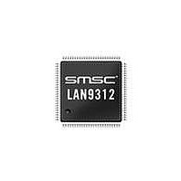
LAN9312-NZW SMSC, LAN9312-NZW Datasheet - Page 168

LAN9312-NZW
Manufacturer Part Number
LAN9312-NZW
Description
Ethernet ICs Hi Per 2 Port 10/100 Ethernet Switch
Manufacturer
SMSC
Type
Two Port Managed Ethernet Switchr
Datasheet
1.LAN9312-NZW.pdf
(458 pages)
Specifications of LAN9312-NZW
Ethernet Connection Type
10 Base-T, 100 Base-TX
Minimum Operating Temperature
0 C
Mounting Style
SMD/SMT
Product
Ethernet Switches
Number Of Transceivers
1
Standard Supported
802.3, 802.3u
Data Rate
10 Mbps, 100 Mbps
Supply Voltage (max)
3.3 V
Supply Voltage (min)
0 V
Supply Current (max)
186 mA, 295 mA
Maximum Operating Temperature
+ 70 C
Package / Case
TQFP-100
Lead Free Status / RoHS Status
Lead free / RoHS Compliant
Available stocks
Company
Part Number
Manufacturer
Quantity
Price
Company:
Part Number:
LAN9312-NZW
Manufacturer:
Standard
Quantity:
143
Company:
Part Number:
LAN9312-NZW
Manufacturer:
Microchip Technology
Quantity:
10 000
- Current page: 168 of 458
- Download datasheet (5Mb)
Revision 1.7 (06-29-10)
14.2
ADDRESS
094h - 098h
OFFSET
05Ch
06Ch
07Ch
08Ch
050h
054h
058h
060h
064h
068h
070h
074h
078h
080h
084h
088h
090h
The System CSR’s are directly addressable memory mapped registers with a base address offset
range of 050h to 2DCh. These registers are addressable by the Host via the Host Bus Interface (HBI).
Table 14.1
reset to their default value on the assertion of a chip-level reset.
The System CSR’s can be divided into 9 sub-categories. Each of these sub-categories contains the
System CSR descriptions of the associated registers. The register descriptions are categorized as
follows:
System Control and Status Registers
Section 14.2.1, "Interrupts," on page 172
Section 14.2.2, "Host MAC & FIFO’s," on page 180
Section 14.2.3, "GPIO/LED," on page 192
Section 14.2.4, "EEPROM," on page 197
Section 14.2.5, "IEEE 1588," on page 201
Section 14.2.6, "Switch Fabric," on page 229
Section 14.2.7, "PHY Management Interface (PMI)," on page 243
Section 14.2.8, "Virtual PHY," on page 245
Section 14.2.9, "Miscellaneous," on page 259
lists the System CSR’s and their corresponding addresses in order. All system CSR’s are
RX_DP_CTRL
RX_FIFO_INF
TX_FIFO_INF
Table 14.1 System Control and Status Registers
BYTE_TEST
RESERVED
RESERVED
RESERVED
PMT_CTRL
SYMBOL
GPT_CFG
GPT_CNT
IRQ_CFG
FIFO_INT
HW_CFG
INT_STS
RX_CFG
TX_CFG
ID_REV
INT_EN
High Performance Two Port 10/100 Managed Ethernet Switch with 32-Bit Non-PCI CPU Interface
DATASHEET
168
Chip ID and Revision Register,
Interrupt Configuration Register,
Interrupt Status Register,
Interrupt Enable Register,
Reserved for Future Use
Byte Order Test Register,
FIFO Level Interrupts Register,
Receive Configuration Register,
Transmit Configuration Register,
Hardware Configuration Register,
RX Datapath Control Register,
Receive FIFO Information
Transmit FIFO Information Register,
Power Management Control Register,
Reserved for Future Use
General Purpose Timer Configuration Register,
Section 14.2.9.5
General Purpose Timer Count Register,
Reserved for Future Use
REGISTER NAME
Section 14.2.1.2
Section 14.2.9.2
Section 14.2.1.3
Register,Section 14.2.2.4
Section 14.2.2.3
Section 14.2.1.4
Section 14.2.9.1
Section 14.2.2.1
Section 14.2.1.1
Section 14.2.2.2
Section 14.2.9.3
Section 14.2.2.5
Section 14.2.9.4
Section 14.2.9.6
SMSC LAN9312
Datasheet
Related parts for LAN9312-NZW
Image
Part Number
Description
Manufacturer
Datasheet
Request
R

Part Number:
Description:
Ethernet ICs Hi Per 2 Port 10/100 Ethernet Switch
Manufacturer:
SMSC
Datasheet:

Part Number:
Description:
FAST ETHERNET PHYSICAL LAYER DEVICE
Manufacturer:
SMSC Corporation
Datasheet:

Part Number:
Description:
357-036-542-201 CARDEDGE 36POS DL .156 BLK LOPRO
Manufacturer:
SMSC Corporation
Datasheet:

Part Number:
Description:
357-036-542-201 CARDEDGE 36POS DL .156 BLK LOPRO
Manufacturer:
SMSC Corporation
Datasheet:

Part Number:
Description:
357-036-542-201 CARDEDGE 36POS DL .156 BLK LOPRO
Manufacturer:
SMSC Corporation
Datasheet:

Part Number:
Description:
4-PORT USB2.0 HUB CONTROLLER
Manufacturer:
SMSC Corporation
Datasheet:

Part Number:
Description:
Manufacturer:
SMSC Corporation
Datasheet:

Part Number:
Description:
Manufacturer:
SMSC Corporation
Datasheet:

Part Number:
Description:
FDC37C672ENHANCED SUPER I/O CONTROLLER WITH FAST IR
Manufacturer:
SMSC Corporation
Datasheet:

Part Number:
Description:
COM90C66LJPARCNET Controller/Transceiver with AT Interface and On-Chip RAM
Manufacturer:
SMSC Corporation
Datasheet:

Part Number:
Description:
Manufacturer:
SMSC Corporation
Datasheet:

Part Number:
Description:
Manufacturer:
SMSC Corporation
Datasheet:

Part Number:
Description:
Manufacturer:
SMSC Corporation
Datasheet:

Part Number:
Description:
Manufacturer:
SMSC Corporation
Datasheet:


