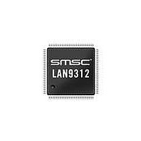
LAN9312-NZW SMSC, LAN9312-NZW Datasheet - Page 41

LAN9312-NZW
Manufacturer Part Number
LAN9312-NZW
Description
Ethernet ICs Hi Per 2 Port 10/100 Ethernet Switch
Manufacturer
SMSC
Type
Two Port Managed Ethernet Switchr
Datasheet
1.LAN9312-NZW.pdf
(458 pages)
Specifications of LAN9312-NZW
Ethernet Connection Type
10 Base-T, 100 Base-TX
Minimum Operating Temperature
0 C
Mounting Style
SMD/SMT
Product
Ethernet Switches
Number Of Transceivers
1
Standard Supported
802.3, 802.3u
Data Rate
10 Mbps, 100 Mbps
Supply Voltage (max)
3.3 V
Supply Voltage (min)
0 V
Supply Current (max)
186 mA, 295 mA
Maximum Operating Temperature
+ 70 C
Package / Case
TQFP-100
Lead Free Status / RoHS Status
Lead free / RoHS Compliant
Available stocks
Company
Part Number
Manufacturer
Quantity
Price
Company:
Part Number:
LAN9312-NZW
Manufacturer:
Standard
Quantity:
143
Company:
Part Number:
LAN9312-NZW
Manufacturer:
Microchip Technology
Quantity:
10 000
- Current page: 41 of 458
- Download datasheet (5Mb)
High Performance Two Port 10/100 Managed Ethernet Switch with 32-Bit Non-PCI CPU Interface
Datasheet
SMSC LAN9312
STRAP NAME
LED_en_strap[7:0]
LED_fun_strap[1:0]
auto_mdix_strap_1
manual_mdix_strap_1
autoneg_strap_1
Table 4.2 Soft-Strap Configuration Strap Definitions
DESCRIPTION
LED Enable Straps: Configures the default value for the
LED_EN bits in the
(LED_CFG). A high value configures the associated
LED/GPIO pin as a LED. A low value configures the
associated LED/GPIO pin as a GPIO.
Note:
LED Function Straps: Configures the default value for the
LED_FUN bits in the
(LED_CFG). When configured low, the corresponding bit
will be cleared. When configured high, the corresponding
bit will be set.
Port 1 Auto-MDIX Enable Strap: Configures the default
value for the Auto-MDIX functionality on Port 1 when the
AMDIXCTL bit in the
Indication Register
(PHY_SPECIAL_CONTROL_STAT_IND_x)
When configured low, Auto-MDIX is disabled. When
configured high, Auto-MDIX is enabled.
Note:
Port 1 Manual MDIX Strap: Configures MDI(0) or MDIX(1)
for Port 1 when the auto_mdix_strap_1 is low and the
AMDIXCTL bit of the
Indication Register
(PHY_SPECIAL_CONTROL_STAT_IND_x)
Port 1 Auto Negotiation Enable Strap: Configures the
default value for the
in the PHY_BASIC_CTRL_1 register (See
Section
disabled. When configured high, auto-negotiation is
enabled.
This strap also affects the default value of the following bits:
Refer to the respective register definition sections for
additional information.
PHY_SPEED_SEL_LSB and PHY_DUPLEX bits of the
Port x PHY Basic Control Register
(PHY_BASIC_CONTROL_x)
10BASE-T Full Duplex (bit 6) and 10BASE-T Half Duplex
(bit 5) bits of the
Advertisement Register (PHY_AN_ADV_x)
MODE[2:0] bits of the
(PHY_SPECIAL_MODES_x)
14.4.2.1). When configured low, auto-negotiation is
One pin configures the default for all 8
LED/GPIOs, but 8 separate bits are loaded by the
EEPROM Loader, allowing individual control over
each LED/GPIO.
If AMDIXCTL is set, this strap had no effect.
DATASHEET
Port x PHY Auto-Negotiation
LED Configuration Register
Auto-Negotiation (PHY_AN)
LED Configuration Register
Port x PHY Special Control/Status
Port x PHY Special Control/Status
Port x PHY Special Modes Register
41
is cleared.
is cleared.
enable bit
PIN / DEFAULT
VALUE
LED_EN
00b
AUTO_MDIX_1
0b
1b
Revision 1.7 (06-29-10)
Related parts for LAN9312-NZW
Image
Part Number
Description
Manufacturer
Datasheet
Request
R

Part Number:
Description:
Ethernet ICs Hi Per 2 Port 10/100 Ethernet Switch
Manufacturer:
SMSC
Datasheet:

Part Number:
Description:
FAST ETHERNET PHYSICAL LAYER DEVICE
Manufacturer:
SMSC Corporation
Datasheet:

Part Number:
Description:
357-036-542-201 CARDEDGE 36POS DL .156 BLK LOPRO
Manufacturer:
SMSC Corporation
Datasheet:

Part Number:
Description:
357-036-542-201 CARDEDGE 36POS DL .156 BLK LOPRO
Manufacturer:
SMSC Corporation
Datasheet:

Part Number:
Description:
357-036-542-201 CARDEDGE 36POS DL .156 BLK LOPRO
Manufacturer:
SMSC Corporation
Datasheet:

Part Number:
Description:
4-PORT USB2.0 HUB CONTROLLER
Manufacturer:
SMSC Corporation
Datasheet:

Part Number:
Description:
Manufacturer:
SMSC Corporation
Datasheet:

Part Number:
Description:
Manufacturer:
SMSC Corporation
Datasheet:

Part Number:
Description:
FDC37C672ENHANCED SUPER I/O CONTROLLER WITH FAST IR
Manufacturer:
SMSC Corporation
Datasheet:

Part Number:
Description:
COM90C66LJPARCNET Controller/Transceiver with AT Interface and On-Chip RAM
Manufacturer:
SMSC Corporation
Datasheet:

Part Number:
Description:
Manufacturer:
SMSC Corporation
Datasheet:

Part Number:
Description:
Manufacturer:
SMSC Corporation
Datasheet:

Part Number:
Description:
Manufacturer:
SMSC Corporation
Datasheet:

Part Number:
Description:
Manufacturer:
SMSC Corporation
Datasheet:


