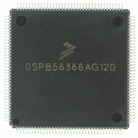
DSPB56366AG120 Freescale Semiconductor, DSPB56366AG120 Datasheet - Page 24

DSPB56366AG120
Manufacturer Part Number
DSPB56366AG120
Description
IC DSP 24BIT AUD 120MHZ 144-LQFP
Manufacturer
Freescale Semiconductor
Series
Symphony™r
Type
Audio Processorr
Datasheet
1.DSPB56366AG120.pdf
(110 pages)
Specifications of DSPB56366AG120
Interface
Host Interface, I²C, SAI, SPI
Clock Rate
120MHz
Non-volatile Memory
ROM (240 kB)
On-chip Ram
69kB
Voltage - I/o
3.30V
Voltage - Core
3.30V
Operating Temperature
-40°C ~ 110°C
Mounting Type
Surface Mount
Package / Case
144-LQFP
Lead Free Status / RoHS Status
Lead free / RoHS Compliant
Available stocks
Company
Part Number
Manufacturer
Quantity
Price
Company:
Part Number:
DSPB56366AG120
Manufacturer:
TOSHIBA
Quantity:
639
Company:
Part Number:
DSPB56366AG120
Manufacturer:
FREESCAL
Quantity:
273
Company:
Part Number:
DSPB56366AG120
Manufacturer:
Freescale Semiconductor
Quantity:
10 000
2.11
2.12
2-20
Signal
Name
Signal
Name
ADO
PD0
PD1
TIO0
ACI
SPDIF Transmitter Digital Audio Interface
Timer
Input, output, or
Input, output, or
disconnected
disconnected
Input or Output
Output
Type
Input
Type
Disconnected
Disconnected
Disconnected
Disconnected
State During
State during
Table 2-13 Digital Audio Interface (DAX) Signals
Reset
Reset
GPIO
GPIO
GPIO
GPIO
Input
DSP56366 Technical Data, Rev. 3.1
Table 2-14 Timer Signal
Audio Clock Input—This is the DAX clock input. When programmed to use
an external clock, this input supplies the DAX clock. The external clock
frequency must be 256, 384, or 512 times the audio sampling frequency
(256 × Fs, 384 × Fs or 512 × Fs, respectively).
Port D 0—When the DAX is configured as GPIO, this signal is individually
programmable as input, output, or internally disconnected.
The default state after reset is GPIO disconnected.
This input is 5 V tolerant.
Digital Audio Data Output—This signal is an audio and non-audio output
in the form of AES/EBU, CP340 and IEC958 data in a biphase mark format.
Port D 1—When the DAX is configured as GPIO, this signal is individually
programmable as input, output, or internally disconnected.
The default state after reset is GPIO disconnected.
This input is 5 V tolerant.
Timer 0 Schmitt-Trigger Input/Output—When timer 0 functions as an
external event counter or in measurement mode, TIO0 is used as input.
When timer 0 functions in watchdog, timer, or pulse modulation mode, TIO0
is used as output.
The default mode after reset is GPIO input. This can be changed to output or
configured as a timer input/output through the timer 0 control/status register
(TCSR0). If TIO0 is not being used, it is recommended to either define it as
GPIO output immediately at the beginning of operation or leave it defined as
GPIO input but connected to Vcc through a pull-up resistor in order to ensure
a stable logic level at this input.
This input is 5 V tolerant.
Signal Description
Signal Description
Freescale Semiconductor


