DSPB56366AG120 Freescale Semiconductor, DSPB56366AG120 Datasheet - Page 9
DSPB56366AG120
Manufacturer Part Number
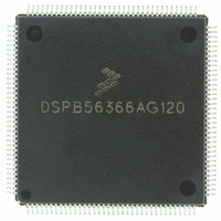
DSPB56366AG120
Description
IC DSP 24BIT AUD 120MHZ 144-LQFP
Manufacturer
Freescale Semiconductor
Series
Symphony™r
Type
Audio Processorr
Datasheet
1.DSPB56366AG120.pdf
(110 pages)
Specifications of DSPB56366AG120
Interface
Host Interface, I²C, SAI, SPI
Clock Rate
120MHz
Non-volatile Memory
ROM (240 kB)
On-chip Ram
69kB
Voltage - I/o
3.30V
Voltage - Core
3.30V
Operating Temperature
-40°C ~ 110°C
Mounting Type
Surface Mount
Package / Case
144-LQFP
Lead Free Status / RoHS Status
Lead free / RoHS Compliant
Available stocks
Company
Part Number
Manufacturer
Quantity
Price
Company:

Part Number:
DSPB56366AG120
Manufacturer:
TOSHIBA
Quantity:
639
Company:
Part Number:
DSPB56366AG120
Manufacturer:
FREESCAL
Quantity:
273
Company:
Part Number:
DSPB56366AG120
Manufacturer:
Freescale Semiconductor
Quantity:
10 000


2.5.1
2.5.2
2.5.3
Freescale Semiconductor
Signal Name
RAS0–RAS2
AA0–AA2/
A0–A17
D0–D23
Signal
Name
Signal
Name
CAS
WR
RD
External Address Bus
External Data Bus
External Bus Control
Input/Output
Output
Type
Output
Output
Output
Output
Type
Type
Tri-stated
during
State during
Reset
State
Tri-stated
Tri-stated
Tri-stated
Tri-stated
Tri-stated
during
Reset
Reset
State
Table 2-5 External Address Bus Signals
Table 2-7 External Bus Control Signals
Table 2-6 External Data Bus Signals
Address Bus—When the DSP is the bus master, A0–A17 are active-high outputs
that specify the address for external program and data memory accesses.
Otherwise, the signals are tri-stated. To minimize power dissipation, A0–A17 do not
change state when external memory spaces are not being accessed.
DSP56366 Technical Data, Rev. 3.1
Data Bus—When the DSP is the bus master, D0–D23 are active-high,
bidirectional input/outputs that provide the bidirectional data bus for external
program and data memory accesses. Otherwise, D0–D23 are tri-stated.
Address Attribute or Row Address Strobe—When defined as AA, these
signals can be used as chip selects or additional address lines. When defined
as RAS, these signals can be used as RAS for DRAM interface. These signals
are tri-statable outputs with programmable polarity.
Column Address Strobe— When the DSP is the bus master, CAS is an
active-low output used by DRAM to strobe the column address. Otherwise, if the
bus mastership enable (BME) bit in the DRAM control register is cleared, the
signal is tri-stated.
Read Enable—When the DSP is the bus master, RD is an active-low output
that is asserted to read external memory on the data bus (D0-D23). Otherwise,
RD is tri-stated.
Write Enable—When the DSP is the bus master, WR is an active-low output
that is asserted to write external memory on the data bus (D0-D23). Otherwise,
WR is tri-stated.
Signal Description
Signal Description
Signal Description
2-5
Related parts for DSPB56366AG120
Image
Part Number
Description
Manufacturer
Datasheet
Request
R

Part Number:
Description:
Manufacturer:
Freescale Semiconductor, Inc
Datasheet:
Part Number:
Description:
Manufacturer:
Freescale Semiconductor, Inc
Datasheet:
Part Number:
Description:
Manufacturer:
Freescale Semiconductor, Inc
Datasheet:
Part Number:
Description:
Manufacturer:
Freescale Semiconductor, Inc
Datasheet:
Part Number:
Description:
Manufacturer:
Freescale Semiconductor, Inc
Datasheet:
Part Number:
Description:
Manufacturer:
Freescale Semiconductor, Inc
Datasheet:
Part Number:
Description:
Manufacturer:
Freescale Semiconductor, Inc
Datasheet:
Part Number:
Description:
Manufacturer:
Freescale Semiconductor, Inc
Datasheet:
Part Number:
Description:
Manufacturer:
Freescale Semiconductor, Inc
Datasheet:
Part Number:
Description:
Manufacturer:
Freescale Semiconductor, Inc
Datasheet:
Part Number:
Description:
Manufacturer:
Freescale Semiconductor, Inc
Datasheet:
Part Number:
Description:
Manufacturer:
Freescale Semiconductor, Inc
Datasheet:
Part Number:
Description:
Manufacturer:
Freescale Semiconductor, Inc
Datasheet:
Part Number:
Description:
Manufacturer:
Freescale Semiconductor, Inc
Datasheet:
Part Number:
Description:
Manufacturer:
Freescale Semiconductor, Inc
Datasheet: