DSPB56366AG120 Freescale Semiconductor, DSPB56366AG120 Datasheet - Page 97
DSPB56366AG120
Manufacturer Part Number
DSPB56366AG120
Description
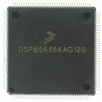
IC DSP 24BIT AUD 120MHZ 144-LQFP
Manufacturer
Freescale Semiconductor
Series
Symphony™r
Type
Audio Processorr
Datasheet
1.DSPB56366AG120.pdf
(110 pages)
Specifications of DSPB56366AG120
Interface
Host Interface, I²C, SAI, SPI
Clock Rate
120MHz
Non-volatile Memory
ROM (240 kB)
On-chip Ram
69kB
Voltage - I/o
3.30V
Voltage - Core
3.30V
Operating Temperature
-40°C ~ 110°C
Mounting Type
Surface Mount
Package / Case
144-LQFP
Lead Free Status / RoHS Status
Lead free / RoHS Compliant
Available stocks
Company
Part Number
Manufacturer
Quantity
Price
Company:

Part Number:
DSPB56366AG120
Manufacturer:
TOSHIBA
Quantity:
639
Company:
Part Number:
DSPB56366AG120
Manufacturer:
FREESCAL
Quantity:
273
Company:
Part Number:
DSPB56366AG120
Manufacturer:
Freescale Semiconductor
Quantity:
10 000


5
5.1
An estimation of the chip junction temperature, T
Where:
Historically, thermal resistance has been expressed as the sum of a junction-to-case thermal resistance and
a case-to-ambient thermal resistance.
Where:
R
change the case-to-ambient thermal resistance, R
the device, add a heat sink, change the mounting arrangement on the printed circuit board (PCB), or
otherwise change the thermal dissipation capability of the area surrounding the device on a PCB. This
model is most useful for ceramic packages with heat sinks; some 90% of the heat flow is dissipated through
the case to the heat sink and out to the ambient environment. For ceramic packages, in situations where
the heat flow is split between a path to the case and an alternate path through the PCB, analysis of the
device thermal performance may need the additional modeling capability of a system level thermal
simulation tool.
The thermal performance of plastic packages is more dependent on the temperature of the PCB to which
the package is mounted. Again, if the estimations obtained from R
the thermal performance is adequate, a system level model may be appropriate.
A complicating factor is the existence of three common ways for determining the junction-to-case thermal
resistance in plastic packages.
Freescale Semiconductor
θJC
•
is device-related and cannot be influenced by the user. The user controls the thermal environment to
Design Considerations
To minimize temperature variation across the surface, the thermal resistance is measured from the
junction to the outside surface of the package (case) closest to the chip mounting area when that
surface has a proper heat sink.
Thermal Design Considerations
T
R
P
R
R
R
A
D
qJA
θJA
θJC
θCA
= ambient temperature °C
= package junction-to-ambient thermal resistance °C/W
= power dissipation in package W
= package junction-to-ambient thermal resistance °C/W
= package junction-to-case thermal resistance °C/W
= package case-to-ambient thermal resistance °C/W
DSP56366 Technical Data, Rev. 3.1
T
R
J
θJA
=
T
=
A
θCA
J
+
R
, in °C can be obtained from the following equation:
(
θJC
. For example, the user can change the air flow around
P
D
+
×
R
R
θCA
θJA
)
θJA
do not satisfactorily answer whether
5-1
Related parts for DSPB56366AG120
Image
Part Number
Description
Manufacturer
Datasheet
Request
R

Part Number:
Description:
Manufacturer:
Freescale Semiconductor, Inc
Datasheet:
Part Number:
Description:
Manufacturer:
Freescale Semiconductor, Inc
Datasheet:
Part Number:
Description:
Manufacturer:
Freescale Semiconductor, Inc
Datasheet:
Part Number:
Description:
Manufacturer:
Freescale Semiconductor, Inc
Datasheet:
Part Number:
Description:
Manufacturer:
Freescale Semiconductor, Inc
Datasheet:
Part Number:
Description:
Manufacturer:
Freescale Semiconductor, Inc
Datasheet:
Part Number:
Description:
Manufacturer:
Freescale Semiconductor, Inc
Datasheet:
Part Number:
Description:
Manufacturer:
Freescale Semiconductor, Inc
Datasheet:
Part Number:
Description:
Manufacturer:
Freescale Semiconductor, Inc
Datasheet:
Part Number:
Description:
Manufacturer:
Freescale Semiconductor, Inc
Datasheet:
Part Number:
Description:
Manufacturer:
Freescale Semiconductor, Inc
Datasheet:
Part Number:
Description:
Manufacturer:
Freescale Semiconductor, Inc
Datasheet:
Part Number:
Description:
Manufacturer:
Freescale Semiconductor, Inc
Datasheet:
Part Number:
Description:
Manufacturer:
Freescale Semiconductor, Inc
Datasheet:
Part Number:
Description:
Manufacturer:
Freescale Semiconductor, Inc
Datasheet: