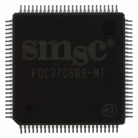
FDC37C669-MT SMSC, FDC37C669-MT Datasheet - Page 38

FDC37C669-MT
Manufacturer Part Number
FDC37C669-MT
Description
IC CTRLR SUPER I/O FLPPY 100TQFP
Manufacturer
SMSC
Datasheet
1.FDC37C669-MT.pdf
(162 pages)
Specifications of FDC37C669-MT
Controller Type
I/O Controller
Interface
ISA Host
Voltage - Supply
4.5 V ~ 5.5 V
Current - Supply
25mA
Operating Temperature
0°C ~ 70°C
Mounting Type
Surface Mount
Package / Case
100-TQFP, 100-VQFP
Lead Free Status / RoHS Status
Lead free / RoHS Compliant
Other names
638-1008
Available stocks
Company
Part Number
Manufacturer
Quantity
Price
Company:
Part Number:
FDC37C669-MT
Manufacturer:
Microchip Technology
Quantity:
10 000
- Current page: 38 of 162
- Download datasheet (619Kb)
PS/2 mode - (IDENT low, MFM high)
This
configuration and register set. The DMA bit of the DOR
becomes a "don't care", (FINTR and DRQ are always
valid), TC and DENSEL become active low.
Model 30 mode - (IDENT low, MFM low)
This mode supports PS/2 Model 30 configuration and
register set. The DMA enable bit of ther DOR becomes
valid (FINTR and DRQ can be hi Z), TC is active high and
DENSEL is active low.
DMA TRANSFERS
DMA transfers are enabled with the Specify command
and are initiated by the FDC by activating the FDRQ pin
during a data transfer command. The FIFO is enabled
directly by asserting nDACK and addresses need not
be valid.
Note that if the DMA controller (i.e. 8237A) is
programmed to function in verify mode, a pseudo read is
performed by the FDC based only on nDACK.
mode
configured into byte mode (FIFO disabled) and is
programmed to do a read. With the FIFO enabled, the
FDC can perform the above operation by using the new
Verify command; no DMA operation is needed.
CONTROLLER PHASES
For simplicity, command handling in the FDC can be
divided into three phases: Command, Execution, and
Result.
sections.
Command Phase
After a reset, the FDC enters the command phase and is
ready to accept a command from the host. For each of
the
mode
is
Each phase is described in the following
only
commands,
supports
available when the FDC
the
PS/2
a
models
has been
50/60/80
defined
This
38
set of command code bytes and parameter bytes has to
be written to the FDC before the command phase is
complete. (Please refer to Table 18 for the command set
descriptions). These bytes of data must be transferred in
the order prescribed.
Before writing to the FDC, the host must examine the
RQM and DIO bits of the Main Status Register. RQM
and DIO must be equal to "1" and "0" respectively before
command bytes may be written. RQM is set false by the
FDC after each write cycle until the received byte is
processed. The FDC asserts RQM again to request each
parameter byte of the command unless an illegal
command condition is detected. After the last parameter
byte is received, RQM remains "0" and the FDC
automatically enters the next phase as defined by the
command definition.
The FIFO is disabled during the command phase to
provide for the proper handling of the "Invalid Command"
condition.
Execution Phase
All data transfers to or from the FDC occur during the
execution phase, which can proceed in DMA or non-DMA
mode as indicated in the Specify command.
After a reset, the FIFO is disabled. Each data byte is
transferred by an FINT or FDRQ depending on the DMA
mode. The Configure command can enable the FIFO
and set the FIFO threshold value.
The following paragraphs detail the operation of the FIFO
flow control. In these descriptions, <threshold> is defined
as the number of bytes available to the FDC when service
is requested from the host and ranges from 1 to 16. The
parameter FIFOTHR, which the user programs, is one
less and ranges from 0 to 15.
Related parts for FDC37C669-MT
Image
Part Number
Description
Manufacturer
Datasheet
Request
R

Part Number:
Description:
FAST ETHERNET PHYSICAL LAYER DEVICE
Manufacturer:
SMSC Corporation
Datasheet:

Part Number:
Description:
357-036-542-201 CARDEDGE 36POS DL .156 BLK LOPRO
Manufacturer:
SMSC Corporation
Datasheet:

Part Number:
Description:
357-036-542-201 CARDEDGE 36POS DL .156 BLK LOPRO
Manufacturer:
SMSC Corporation
Datasheet:

Part Number:
Description:
357-036-542-201 CARDEDGE 36POS DL .156 BLK LOPRO
Manufacturer:
SMSC Corporation
Datasheet:

Part Number:
Description:
4-PORT USB2.0 HUB CONTROLLER
Manufacturer:
SMSC Corporation
Datasheet:

Part Number:
Description:
Manufacturer:
SMSC Corporation
Datasheet:

Part Number:
Description:
Manufacturer:
SMSC Corporation
Datasheet:

Part Number:
Description:
FDC37C672ENHANCED SUPER I/O CONTROLLER WITH FAST IR
Manufacturer:
SMSC Corporation
Datasheet:

Part Number:
Description:
COM90C66LJPARCNET Controller/Transceiver with AT Interface and On-Chip RAM
Manufacturer:
SMSC Corporation
Datasheet:

Part Number:
Description:
Manufacturer:
SMSC Corporation
Datasheet:

Part Number:
Description:
Manufacturer:
SMSC Corporation
Datasheet:

Part Number:
Description:
Manufacturer:
SMSC Corporation
Datasheet:

Part Number:
Description:
Manufacturer:
SMSC Corporation
Datasheet:


