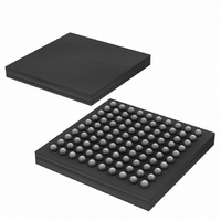
DS3170N+ Maxim Integrated Products, DS3170N+ Datasheet - Page 8

DS3170N+
Manufacturer Part Number
DS3170N+
Description
IC TXRX DS3/E3 100-CSBGA
Manufacturer
Maxim Integrated Products
Datasheet
1.DS3170.pdf
(230 pages)
Specifications of DS3170N+
Function
Single-Chip Transceiver
Interface
DS3, E3
Number Of Circuits
1
Voltage - Supply
3.135 V ~ 3.465 V
Current - Supply
120mA
Operating Temperature
-40°C ~ 85°C
Mounting Type
Surface Mount
Package / Case
100-LBGA
Includes
DS3 Framers, E3 Framers, HDLC Controller, On-Chip BERTs
Lead Free Status / RoHS Status
Lead free / RoHS Compliant
Power (watts)
-
DS3170 DS3/E3 Single-Chip Transceiver
LIST OF TABLES
Table 5-1. Standards Compliance ........................................................................................................................ 16
Table 8-1. DS3170 Short Pin Descriptions ........................................................................................................... 25
Table 8-2. Detailed Pin Descriptions .................................................................................................................... 27
Table 9-1. Configuration of Port Register Settings ................................................................................................ 52
Table 10-1. LIU Enable Table .............................................................................................................................. 57
Table 10-2. All Possible Clock Sources Based on Mode and Loopback ................................................................ 57
Table 10-3. Source Selection of TLCLK Clock Signal ........................................................................................... 58
Table 10-4. Source Selection of TCLKO (Internal Tx Clock) ................................................................................. 59
Table 10-5. Source Selection of RCLKO Clock Signal (Internal Rx Clock) ............................................................ 59
Table 10-6. Transmit Line Interface Signal Pin Valid Timing Source Select ........................................................... 60
Table 10-7. Transmit Framer Pin Signal Timing Source Select ............................................................................. 61
Table 10-8. Receive Line Interface Pin Signal Timing Source Select .................................................................... 61
Table 10-9. Receive Framer Pin Signal Timing Source Select .............................................................................. 62
Table 10-10. Reset and Power-Down Sources ..................................................................................................... 65
Table 10-11. CLAD Clock Source Settings ........................................................................................................... 66
Table 10-12. Global 8 kHz Reference Source Table ............................................................................................. 67
Table 10-13. Port 8 kHz Reference Source Table ................................................................................................. 67
Table 10-14. GPIO Global Signals ....................................................................................................................... 68
Table 10-15. GPIO Pin Global Mode Select Bits ................................................................................................... 68
Table 10-16. GPIO Port Alarm Monitor Select ...................................................................................................... 69
Table 10-17. Loopback Mode Selections .............................................................................................................. 71
Table 10-18. Line AIS Enable Modes ................................................................................................................... 75
Table 10-19. Payload (Downstream) AIS Enable Modes ...................................................................................... 75
Table 10-20. TSOFI Input Pin Functions .............................................................................................................. 76
Table 10-21. TSOFO/TDEN/Output Pin Functions ................................................................................................ 76
Table 10-22 TCLKO/TGCLK Output Pin Functions ............................................................................................... 76
Table 10-23. RSOFO/RDEN Output Pin Functions ............................................................................................... 77
Table 10-24. RCLKO/RGCLK Output Pin Functions ............................................................................................. 77
Table 10-25. Framing Mode Select Bits FM[2:0] ................................................................................................... 77
Table 10-26. Line Mode Select Bits LM[2:0] ......................................................................................................... 78
Table 10-27. C-Bit DS3 Frame Overhead Bit Definitions ....................................................................................... 85
Table 10-28. M23 DS3 Frame Overhead Bit Definitions ....................................................................................... 87
Table 10-29. G.832 E3 Frame Overhead Bit Definitions ....................................................................................... 92
Table 10-30. Payload Label Match Status ............................................................................................................ 96
Table 10-31. Pseudo-Random Pattern Generation ............................................................................................. 109
Table 10-32. Repetitive Pattern Generation ........................................................................................................ 109
Table 10-33. Transformer Characteristics ........................................................................................................... 114
Table 10-34. Recommended Transformers ........................................................................................................ 115
Table 11-1. Register Address Map ..................................................................................................................... 117
Table 12-1. Global Register Bit Map ................................................................................................................... 119
Table 12-2. Port Register Bit Map ...................................................................................................................... 119
Table 12-3. BERT Register Bit Map ................................................................................................................... 120
Table 12-4. Line Register Bit Map ..................................................................................................................... 121
Table 12-5. HDLC Register Bit Map ................................................................................................................... 121
Table 12-6. FEAC Register Bit Map ................................................................................................................... 122
Table 12-7. Trail Trace Register Bit Map ............................................................................................................ 123
Table 12-8. T3 Register Bit Map ......................................................................................................................... 123
Table 12-9. E3 G.751 Register Bit Map .............................................................................................................. 124
Table 12-10. E3 G.832 Register Bit Map ............................................................................................................ 125
Table 12-11. Global Register Map ...................................................................................................................... 126
Table 12-12. Port Register Map ......................................................................................................................... 133
Table 12-13. BERT Register Map ...................................................................................................................... 144
Table 12-14. Transmit Side B3ZS/HDB3 Line Encoder/Decoder Register Map ................................................... 151
Table 12-15. Receive Side B3ZS/HDB3 Line Encoder/Decoder Register Map .................................................... 152
Table 12-16. Transmit Side HDLC Register Map ................................................................................................ 156
Table 12-17. Receive Side HDLC Register Map ................................................................................................. 159
Table 12-18. FEAC Transmit Side Register Map ................................................................................................ 163
8 of 230


