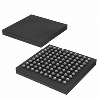
DS3170N+ Maxim Integrated Products, DS3170N+ Datasheet - Page 81

DS3170N+
Manufacturer Part Number
DS3170N+
Description
IC TXRX DS3/E3 100-CSBGA
Manufacturer
Maxim Integrated Products
Datasheet
1.DS3170.pdf
(230 pages)
Specifications of DS3170N+
Function
Single-Chip Transceiver
Interface
DS3, E3
Number Of Circuits
1
Voltage - Supply
3.135 V ~ 3.465 V
Current - Supply
120mA
Operating Temperature
-40°C ~ 85°C
Mounting Type
Surface Mount
Package / Case
100-LBGA
Includes
DS3 Framers, E3 Framers, HDLC Controller, On-Chip BERTs
Lead Free Status / RoHS Status
Lead free / RoHS Compliant
Power (watts)
-
- Current page: 81 of 230
- Download datasheet (3Mb)
Figure 10-13. DS3 Frame Format
The subframe framer continually searches four adjacent bit positions for a subframe boundary. A subframe
alignment bit (F-bit) checker checks each bit position. All four bit positions must fail before any other bit positions
are checked for a subframe boundary. There are 170 possible bit positions that must be checked, and four
positions are checked simultaneously. Therefore up to 43 checks may be needed to identify the subframe
boundary. The subframe framer enables the multiframe frame once it has identified a subframe boundary. Refer to
Figure 10-14
Figure 10-14. DS3 Subframe Framer State Diagram
The multiframe framer checks for a multiframe boundary. When the multiframe framer identifies a multiframe
boundary, it updates the data path frame counters if either an OOF or OOMF condition is present. The multiframe
framer waits until a subframe boundary has been identified. Then, each bit position is checked for the multiframe
M
M
M
X
X
P
P
1
2
1
2
1
2
3
Verify
F
F
F
F
F
F
F
for the subframe framer state diagram.
11
21
31
41
51
61
71
C
C
C
C
C
C
C
11
21
31
41
51
61
71
All 4 bit positions failed
2 F-bits loaded
Sync
F
F
F
F
F
F
F
12
22
32
42
52
62
72
680 Bits
C
C
C
C
C
C
C
12
22
32
42
52
62
72
81 of 230
Load
F
F
F
F
F
F
F
13
23
33
43
53
63
73
DS3170 DS3/E3 Single-Chip Transceiver
C
C
C
C
C
C
C
13
23
33
43
53
63
73
F
F
F
F
F
F
F
14
24
34
44
54
64
74
7 Sub-
Frames
Related parts for DS3170N+
Image
Part Number
Description
Manufacturer
Datasheet
Request
R

Part Number:
Description:
IC TXRX DS3/E3 100-CSBGA
Manufacturer:
Maxim Integrated Products
Datasheet:

Part Number:
Description:
Network Controller & Processor ICs DS3-E3 Single-Chip T ransceiver T3-E3 Fra
Manufacturer:
Maxim Integrated Products
Datasheet:

Part Number:
Description:
MAX7528KCWPMaxim Integrated Products [CMOS Dual 8-Bit Buffered Multiplying DACs]
Manufacturer:
Maxim Integrated Products
Datasheet:

Part Number:
Description:
Single +5V, fully integrated, 1.25Gbps laser diode driver.
Manufacturer:
Maxim Integrated Products
Datasheet:

Part Number:
Description:
Single +5V, fully integrated, 155Mbps laser diode driver.
Manufacturer:
Maxim Integrated Products
Datasheet:

Part Number:
Description:
VRD11/VRD10, K8 Rev F 2/3/4-Phase PWM Controllers with Integrated Dual MOSFET Drivers
Manufacturer:
Maxim Integrated Products
Datasheet:

Part Number:
Description:
Highly Integrated Level 2 SMBus Battery Chargers
Manufacturer:
Maxim Integrated Products
Datasheet:

Part Number:
Description:
Current Monitor and Accumulator with Integrated Sense Resistor; ; Temperature Range: -40°C to +85°C
Manufacturer:
Maxim Integrated Products

Part Number:
Description:
TSSOP 14/A°/RS-485 Transceivers with Integrated 100O/120O Termination Resis
Manufacturer:
Maxim Integrated Products

Part Number:
Description:
TSSOP 14/A°/RS-485 Transceivers with Integrated 100O/120O Termination Resis
Manufacturer:
Maxim Integrated Products

Part Number:
Description:
QFN 16/A°/AC-DC and DC-DC Peak-Current-Mode Converters with Integrated Step
Manufacturer:
Maxim Integrated Products

Part Number:
Description:
TDFN/A/65V, 1A, 600KHZ, SYNCHRONOUS STEP-DOWN REGULATOR WITH INTEGRATED SWI
Manufacturer:
Maxim Integrated Products

Part Number:
Description:
Integrated Temperature Controller f
Manufacturer:
Maxim Integrated Products

Part Number:
Description:
SOT23-6/I°/45MHz to 650MHz, Integrated IF VCOs with Differential Output
Manufacturer:
Maxim Integrated Products

Part Number:
Description:
SOT23-6/I°/45MHz to 650MHz, Integrated IF VCOs with Differential Output
Manufacturer:
Maxim Integrated Products


