CRD4525-Q1 Cirrus Logic Inc, CRD4525-Q1 Datasheet - Page 27
CRD4525-Q1
Manufacturer Part Number
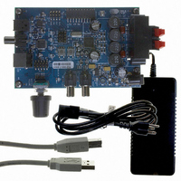
CRD4525-Q1
Description
REFERENCE BOARD FOR CS4525 PWM
Manufacturer
Cirrus Logic Inc
Series
Popguard®r
Specifications of CRD4525-Q1
Amplifier Type
Class D
Output Type
2-Channel (Stereo)
Max Output Power X Channels @ Load
15W x 2 @ 8 Ohm
Voltage - Supply
12 V ~ 18 V
Operating Temperature
0°C ~ 70°C
Board Type
Fully Populated
Utilized Ic / Part
CS4525
Lead Free Status / RoHS Status
Contains lead / RoHS non-compliant
Other names
598-1586


DS726PP3
6.1.1.2
In this mode, the CS4525 will automatically drive the generated internal clock out of the SYS_CLK pin.
This can be disabled with the EnSysClk bit which will cause the SYS_CLK pin to become high-impedance.
Also, the DivSysClk bit allows the frequency of the generated internal clock to be divided by 2 prior to be-
ing driven out of the SYS_CLK.
It should be noted that the internal oscillator driver is disabled when the CS4525 is in reset (RST is low).
Any external devices connected to the SYS_CLK output will not receive a clock signal until the CS4525
is taken out of reset.
Figure 13
To use an external crystal in conjunction with the internal crystal driver, a 20 pF fundamental mode par-
allel resonant crystal must be connected between the XTI and XTO pins. This crystal must oscillate within
the frequency ranges specified in the XTI switching specifications table on
the crystal and its load capacitors should be connected to XTI and XTO. The SYS_CLK pin should be
connected to ground through a 22 kΩ pull-down resistor to prevent the CS4525 from recognizing system
noise on the SYS_CLK pin as a valid clocking signal.
If an external crystal is connected to the XTI/XTO pins while an input clock signal is present on the
SYS_CLK pin following the release of RST, then the CS4525 will automatically use the SYS_CLK pin for
its internal clock. Refer to
Referenced Control
EnSysClk.............................
DivSysClk............................
below demonstrates a typical clocking configuration using the crystal oscillator.
Crystal Oscillator Mode
Reset
Figure 13. Typical Crystal Oscillator Clocking Configuration
Register Location
“SYS_CLK Output Enable (EnSysClk)” on page 69
“SYS_CLK Output Divider (DivSysClk)” on page 69
Section 6.1.1.1
XTI
XTO
CS4525
RST
for a details about this mode of operation.
SYS_CLK
Clock_In
DSP
RST
page
23. Nothing other than
CS4525
27
Related parts for CRD4525-Q1
Image
Part Number
Description
Manufacturer
Datasheet
Request
R

Part Number:
Description:
Development Kit
Manufacturer:
Cirrus Logic Inc
Datasheet:
Part Number:
Description:
Development Kit
Manufacturer:
Cirrus Logic Inc
Datasheet:


Part Number:
Description:
High-efficiency PFC + Fluorescent Lamp Driver Reference Design
Manufacturer:
Cirrus Logic Inc
Datasheet:
Part Number:
Description:
Development Kit
Manufacturer:
Cirrus Logic Inc
Datasheet:
Part Number:
Description:
Development Kit
Manufacturer:
Cirrus Logic Inc
Datasheet:

Part Number:
Description:
Development Kit
Manufacturer:
Cirrus Logic Inc
Datasheet:
Part Number:
Description:
Development Kit
Manufacturer:
Cirrus Logic Inc
Datasheet:
Part Number:
Description:
Development Kit
Manufacturer:
Cirrus Logic Inc
Datasheet:
Part Number:
Description:
Audio Modules & Development Tools EvalBd 30W Qd Hlf- Brdg Dig Amp Pwr Stg
Manufacturer:
Cirrus Logic Inc
Datasheet:

Part Number:
Description:
EVALUATION BOARD FOR CS8427
Manufacturer:
Cirrus Logic Inc
Datasheet:

Part Number:
Description:
BOARD EVAL FOR CS8416 RCVR
Manufacturer:
Cirrus Logic Inc
Datasheet:

Part Number:
Description:
EVALUATION BOARD FOR CS8420
Manufacturer:
Cirrus Logic Inc
Datasheet:

Part Number:
Description:
KIT DEVELOPMENT EP9315 ARM9
Manufacturer:
Cirrus Logic Inc
Datasheet: