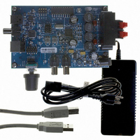
CRD4525-Q1 Cirrus Logic Inc, CRD4525-Q1 Datasheet - Page 56

CRD4525-Q1
Manufacturer Part Number
CRD4525-Q1
Description
REFERENCE BOARD FOR CS4525 PWM
Manufacturer
Cirrus Logic Inc
Series
Popguard®r
Specifications of CRD4525-Q1
Amplifier Type
Class D
Output Type
2-Channel (Stereo)
Max Output Power X Channels @ Load
15W x 2 @ 8 Ohm
Voltage - Supply
12 V ~ 18 V
Operating Temperature
0°C ~ 70°C
Board Type
Fully Populated
Utilized Ic / Part
CS4525
Lead Free Status / RoHS Status
Contains lead / RoHS non-compliant
Other names
598-1586
56
6.2.5
Clocks & Data
Serial Audio
Analog In
EN_TFB
ADC/SP
Stereo
MUTE
I²S/LJ
6.2.5.1
The CS4525 includes a high-pass filter at the beginning of the digital signal processing chain to remove
any DC content from the input signal prior to the remaining internal digital signal processing blocks. The
high-pass filter operates by continuously subtracting a measure of the DC offset from the input signal; it
is always enabled.
6.2.5.2
The CS4525 includes a dedicated MUTE input pin. When low, the PWM outputs will output silence as
modulated signal. When high, the selected input source will be presented at the amplifier outputs.
It should be noted that the auto-mute, soft-ramp, and zero-crossing detection features are active in hard-
ware mode.
6.2.5.3
The CS4525 is capable of reporting various error and warning conditions on its TWR, ERROC, and ER-
RUVTE pins.
The trigger point for each warning and error condition is defined in the
table on
for proper operation.
Digital Signal Flow
In hardware mode, the CS4525 operates as a 2-channel full-bridge PWM amplifier with analog or digital
inputs. Both the PWM outputs and the auxiliary serial outputs are unavailable in hardware mode. To pro-
tect against over-temperature conditions, thermal foldback is included for the internal power stages.
The digital signal flow is shown in
•
•
•
The TWR pin indicates the presence of a thermal warning condition. When active concurrently with the
ERRUVTE pin, indicates a thermal error condition.
The ERROC pin indicates the presence of an over-current condition on one or both of the output chan-
nels.
The ERRUVTE pin indicates the presence of a VP undervoltage condition. When active concurrently
with the TWR pin, indicates a thermal error condition.
Serial Audio
page
Input Port
Multi-Bit
∆Σ ADC
High-Pass Filter
Mute Control
Warning and Error Reporting
20. Each pin implements an active-low open-drain driver and requires an external pull-up
Figure 24. Hardware Mode Digital Signal Flow
+3dB
+3dB
Figure 24
below.
Converter
Converter
Sample
Sample
Rate
Rate
Thermal Foldback
Modulator
Modulator
PWM
PWM
PWM Power Output Characteristics
Drive
Drive
Drive
Drive
Gate
Gate
Gate
Gate
Temp & Current
Sense
Power
Power
Power
Power
Stage
Stage
Stage
Stage
CS4525
DS726PP3
Left
Full-Bridge
Amplifier
Output
Right
Full-Bridge
Amplifier
Output
TWR
ERROC
ERRUVTE


