CRD4525-Q1 Cirrus Logic Inc, CRD4525-Q1 Datasheet - Page 45
CRD4525-Q1
Manufacturer Part Number
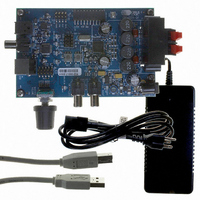
CRD4525-Q1
Description
REFERENCE BOARD FOR CS4525 PWM
Manufacturer
Cirrus Logic Inc
Series
Popguard®r
Specifications of CRD4525-Q1
Amplifier Type
Class D
Output Type
2-Channel (Stereo)
Max Output Power X Channels @ Load
15W x 2 @ 8 Ohm
Voltage - Supply
12 V ~ 18 V
Operating Temperature
0°C ~ 70°C
Board Type
Fully Populated
Utilized Ic / Part
CS4525
Lead Free Status / RoHS Status
Contains lead / RoHS non-compliant
Other names
598-1586


DS726PP3
6.1.7
6.1.7.1
Three PWM power output configurations are supported as shown in
support stereo full-bridge, stereo half-bridge with full-bridge sub, and mono parallel full-bridge output.
The configurations are selected by the OutputCfg[1:0] bits in the Output Cfg register and must only be
changed when the device is in power-down mode (the PDnAll bit is set). Any attempt to write the Out-
putCfg[1:0] bits while the device is powered-up will be ignored.
It should be noted that signals on channels 1, 2 and the sub channel are dependent upon the digital sound
processing blocks being used. For instance, if the 2-way crossover is enabled, channel 1 and 2 contain
the 2-way crossover channel A high- and low-pass outputs respectively. For more information, see the
Digital Sound Processing
6.1.7.2
The CS4525 uses Popguard technology to minimize the effects of power-up and power-down output tran-
sients commonly produced by half-bridge, single supply amplifiers implemented with external DC-block-
ing capacitors connected in series with the audio outputs.
Powered PWM Outputs
The CS4525’s 3 internal modulators can be used to generate multiple powered PWM output configura-
tions to enable a wide variety of system implementations. The CS4525 also implements PWM Popguard
to minimize output transients in half-bridge configurations.
The PWM Popguard feature operates by linearly ramping the PWM power outputs up to and down from
their bias point of VP/2 when a channel is powered up and down respectively using the PDnOutX or PD-
nAll bits. This gradual voltage ramp minimizes output transients while the DC blocking capacitor is
Referenced Control
OutputCfg[1:0].....................
PDnAll .................................
OutputCfg[1:0]
00
01
10
Output Channel Configurations
PWM Popguard Transient Control
1 Ch. Parallel Full-Bridge
Power Configuration
2 Ch. Half-Bridge
2 Ch. Full-Bridge
1 Ch. Full-Bridge
Register Location
“Output Configuration (OutputCfg[1:0])” on page 73
“Power Down (PDnAll)” on page 89
section and
+
Table 8. PWM Power Output Configurations
Figure 14 on page
Output Signal
Sub Channel +
Sub Channel -
Channel 1 +
Channel 2 +
Channel 1 +
Channel 2 +
Channel 1 +
Channel 1 -
Channel 2 -
Channel 1 -
29.
Table 8
below. The configurations
Output Pin(s)
OUT1, OUT2
OUT3, OUT4
OUT1
OUT2
OUT3
OUT4
OUT1
OUT2
OUT3
OUT4
CS4525
45
Related parts for CRD4525-Q1
Image
Part Number
Description
Manufacturer
Datasheet
Request
R

Part Number:
Description:
Development Kit
Manufacturer:
Cirrus Logic Inc
Datasheet:
Part Number:
Description:
Development Kit
Manufacturer:
Cirrus Logic Inc
Datasheet:


Part Number:
Description:
High-efficiency PFC + Fluorescent Lamp Driver Reference Design
Manufacturer:
Cirrus Logic Inc
Datasheet:
Part Number:
Description:
Development Kit
Manufacturer:
Cirrus Logic Inc
Datasheet:
Part Number:
Description:
Development Kit
Manufacturer:
Cirrus Logic Inc
Datasheet:

Part Number:
Description:
Development Kit
Manufacturer:
Cirrus Logic Inc
Datasheet:
Part Number:
Description:
Development Kit
Manufacturer:
Cirrus Logic Inc
Datasheet:
Part Number:
Description:
Development Kit
Manufacturer:
Cirrus Logic Inc
Datasheet:
Part Number:
Description:
Audio Modules & Development Tools EvalBd 30W Qd Hlf- Brdg Dig Amp Pwr Stg
Manufacturer:
Cirrus Logic Inc
Datasheet:

Part Number:
Description:
EVALUATION BOARD FOR CS8427
Manufacturer:
Cirrus Logic Inc
Datasheet:

Part Number:
Description:
BOARD EVAL FOR CS8416 RCVR
Manufacturer:
Cirrus Logic Inc
Datasheet:

Part Number:
Description:
EVALUATION BOARD FOR CS8420
Manufacturer:
Cirrus Logic Inc
Datasheet:

Part Number:
Description:
KIT DEVELOPMENT EP9315 ARM9
Manufacturer:
Cirrus Logic Inc
Datasheet: