CRD4525-Q1 Cirrus Logic Inc, CRD4525-Q1 Datasheet - Page 43
CRD4525-Q1
Manufacturer Part Number
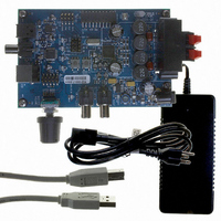
CRD4525-Q1
Description
REFERENCE BOARD FOR CS4525 PWM
Manufacturer
Cirrus Logic Inc
Series
Popguard®r
Specifications of CRD4525-Q1
Amplifier Type
Class D
Output Type
2-Channel (Stereo)
Max Output Power X Channels @ Load
15W x 2 @ 8 Ohm
Voltage - Supply
12 V ~ 18 V
Operating Temperature
0°C ~ 70°C
Board Type
Fully Populated
Utilized Ic / Part
CS4525
Lead Free Status / RoHS Status
Contains lead / RoHS non-compliant
Other names
598-1586


DS726PP3
6.1.5
Auxiliary Serial Output
The CS4525 includes a stereo auxiliary serial output which allows an external device to leverage on its
internal signal processing and routing capabilities. The auxiliary serial output can receive its data from any
of the sources shown in the
The supported output data routing configurations are shown in
is configured to output channels A and B on the auxiliary output data left and right channels respectively.
The data output on each channel of AUX_SDOUT is set by the LChDSel[1:0] and RChDSel[1:0] bits in
the Aux Port Configuration register. The frequencies of AUX_LRCK and AUX_SCLK will vary based upon
the whether the serial input or analog input is being used and the frequency of the system clock for the
CS4525; the nominal values for these clocks are listed in
AUX_LRCK, and AUX_SDOUT are described in the
table on
The auxiliary port can be enabled using the EnAuxPort bit. When enabled, the port operates as a master
and clocks out data in the format dictated by the AuxI²S/LJ bit. When disabled, the AUX_LRCK,
AUX_SCLK, and AUX_SDOUT pins continuously drive a logic ‘0’. It should be noted that when the
CS4525 is configured for analog input, the AUX_LRCK, AUX_SCLK, and AUX_SDOUT pins will contin-
uously drive a logic ‘0’ if either the PDnADC bit or PDnAll bit is set.
Referenced Control
EnAuxPort ...........................
LChDSel[1:0].......................
RChDSel[1:0] ......................
AuxI²S/LJ.............................
PDnADC..............................
PDnAll .................................
Nominal Frequency of AUX_SCLK
Nominal Frequency of AUX_LRCK
LChDSel[1:0]
Applied System Clock from either
SYS_CLK or External Crystal
Frequency of LRCK Input
00
01
10
11
page
Signal
Output
Output
22.
Table 7. Nominal Switching Frequencies of the Auxiliary Serial Output
Aux Left Channel Data
Channel B X-Over LPF
Register Location
“Enable Aux Serial Port (EnAuxPort)” on page 72
“Aux Serial Port Left Channel Data Select (LChDSel[1:0])” on page 73
“Aux Serial Port Right Channel Data Select (RChDSel[1:0])” on page 72
“Aux/Delay Serial Port Digital Interface Format (AuxI²S/LJ)” on page 72
“Power Down ADC (PDnADC)” on page 88
“Power Down (PDnAll)” on page 89
Sub Channel
Channel A
Channel B
Digital Signal Flow
Table 6. Auxiliary Serial Port Data Output
32kHz, 44.1kHz,
Frequency of
Frequency of
18.432, 24.576, or 27.000MHz
SCLK Input
LRCK Input
or 48kHz
(Digital Input Mode)
ADC/SP = 0
diagram on
SCLK Input / 2
LRCK Input / 2
Frequency of
Frequency of
AUX Serial Audio I/O Port Switching Specifications
96kHz
RChDSel[1:0]
page
Table
00
01
10
11
Table 6
29.
7. The characteristics of AUX_SCLK,
18.432MHz
2.304MHz
48kHz
below. By default, the serial port
(Analog Input Mode)
Aux Right Channel Data
Channel B X-Over HPF
Not Applicable
ADC/SP = 1
24.576MHz
3.072MHz
Sub Channel
Channel A
Channel B
48kHz
CS4525
27.000MHz
52.734kHz
3.375MHz
43
Related parts for CRD4525-Q1
Image
Part Number
Description
Manufacturer
Datasheet
Request
R

Part Number:
Description:
Development Kit
Manufacturer:
Cirrus Logic Inc
Datasheet:
Part Number:
Description:
Development Kit
Manufacturer:
Cirrus Logic Inc
Datasheet:


Part Number:
Description:
High-efficiency PFC + Fluorescent Lamp Driver Reference Design
Manufacturer:
Cirrus Logic Inc
Datasheet:
Part Number:
Description:
Development Kit
Manufacturer:
Cirrus Logic Inc
Datasheet:
Part Number:
Description:
Development Kit
Manufacturer:
Cirrus Logic Inc
Datasheet:

Part Number:
Description:
Development Kit
Manufacturer:
Cirrus Logic Inc
Datasheet:
Part Number:
Description:
Development Kit
Manufacturer:
Cirrus Logic Inc
Datasheet:
Part Number:
Description:
Development Kit
Manufacturer:
Cirrus Logic Inc
Datasheet:
Part Number:
Description:
Audio Modules & Development Tools EvalBd 30W Qd Hlf- Brdg Dig Amp Pwr Stg
Manufacturer:
Cirrus Logic Inc
Datasheet:

Part Number:
Description:
EVALUATION BOARD FOR CS8427
Manufacturer:
Cirrus Logic Inc
Datasheet:

Part Number:
Description:
BOARD EVAL FOR CS8416 RCVR
Manufacturer:
Cirrus Logic Inc
Datasheet:

Part Number:
Description:
EVALUATION BOARD FOR CS8420
Manufacturer:
Cirrus Logic Inc
Datasheet:

Part Number:
Description:
KIT DEVELOPMENT EP9315 ARM9
Manufacturer:
Cirrus Logic Inc
Datasheet: