CRD4525-Q1 Cirrus Logic Inc, CRD4525-Q1 Datasheet - Page 62
CRD4525-Q1
Manufacturer Part Number
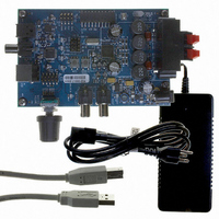
CRD4525-Q1
Description
REFERENCE BOARD FOR CS4525 PWM
Manufacturer
Cirrus Logic Inc
Series
Popguard®r
Specifications of CRD4525-Q1
Amplifier Type
Class D
Output Type
2-Channel (Stereo)
Max Output Power X Channels @ Load
15W x 2 @ 8 Ohm
Voltage - Supply
12 V ~ 18 V
Operating Temperature
0°C ~ 70°C
Board Type
Fully Populated
Utilized Ic / Part
CS4525
Lead Free Status / RoHS Status
Contains lead / RoHS non-compliant
Other names
598-1586


62
6.6
6.6.1
6.6.2
Serial Audio Interfaces
The CS4525 interfaces to external digital audio devices via the serial audio input port and the auxiliary/delay
serial ports.
The serial audio input port provides support for I²S, Left-Justified and Right-Justified data formats and op-
erates in slave mode only, with LRCK and SCLK as inputs. The input LRCK signal must be equal to the
sample rate, Fs and must be synchronous to the serial bit clock, SCLK, which is used to sample the data
bits.
The auxiliary/delay serial port (available in software mode only) supports I²S and Left-Justified data formats
and operates in master mode only, with AUX_LRCK and AUX_SCLK as outputs.
Each of the supported formats is described in detail in sections
Audio Input Port Switching Specifications
page 21
For additional information, application note AN282 presents a tutorial of the 2-channel serial audio interface.
AN282 can be downloaded from the Cirrus Logic web site at http://www.cirrus.com.
I²S Data Format
In I²S format, data is received most significant bit first one SCLK delay after the transition of LRCK and is
valid on the rising edge of SCLK. The left channel data is presented when LRCK is low; the right channel
data is presented when LRCK is high.
Left-Justified Data Format
In Left-Justified format, data is received most significant bit first on the first SCLK after a LRCK transition
and is valid on the rising edge of SCLK. The left channel data is presented when LRCK is high and the
right channel data is presented when LRCK is low.
LRCK
SCLK
LRCK
SDIN
SDIN
SCLK
and
page 22
MSB
MSB
-1 -2 -3 -4 -5
-1 -2 -3 -4 -5
(respectively) for the precise timing and tolerances of each signal.
Figure 31. Left-Justified Serial Audio Formats
+5 +4
+5 +4
Left Channel
Left Channel
Figure 30. I²S Serial Audio Formats
+3 +2 +1
+3 +2 +1
LSB
LSB
and
AUX Serial Audio I/O Port Switching Specifications
6.6.1
MSB
MSB
-1 -2 -3 -4
-1 -2 -3 -4
-
6.6.3
below. Please refer to the
+5 +4
+5 +4
Right Channel
Right Channel
+3 +2 +1
+3 +2 +1
LSB
LSB
CS4525
DS726PP3
Serial
on
Related parts for CRD4525-Q1
Image
Part Number
Description
Manufacturer
Datasheet
Request
R

Part Number:
Description:
Development Kit
Manufacturer:
Cirrus Logic Inc
Datasheet:
Part Number:
Description:
Development Kit
Manufacturer:
Cirrus Logic Inc
Datasheet:


Part Number:
Description:
High-efficiency PFC + Fluorescent Lamp Driver Reference Design
Manufacturer:
Cirrus Logic Inc
Datasheet:
Part Number:
Description:
Development Kit
Manufacturer:
Cirrus Logic Inc
Datasheet:
Part Number:
Description:
Development Kit
Manufacturer:
Cirrus Logic Inc
Datasheet:

Part Number:
Description:
Development Kit
Manufacturer:
Cirrus Logic Inc
Datasheet:
Part Number:
Description:
Development Kit
Manufacturer:
Cirrus Logic Inc
Datasheet:
Part Number:
Description:
Development Kit
Manufacturer:
Cirrus Logic Inc
Datasheet:
Part Number:
Description:
Audio Modules & Development Tools EvalBd 30W Qd Hlf- Brdg Dig Amp Pwr Stg
Manufacturer:
Cirrus Logic Inc
Datasheet:

Part Number:
Description:
EVALUATION BOARD FOR CS8427
Manufacturer:
Cirrus Logic Inc
Datasheet:

Part Number:
Description:
BOARD EVAL FOR CS8416 RCVR
Manufacturer:
Cirrus Logic Inc
Datasheet:

Part Number:
Description:
EVALUATION BOARD FOR CS8420
Manufacturer:
Cirrus Logic Inc
Datasheet:

Part Number:
Description:
KIT DEVELOPMENT EP9315 ARM9
Manufacturer:
Cirrus Logic Inc
Datasheet: