CRD4525-Q1 Cirrus Logic Inc, CRD4525-Q1 Datasheet - Page 49
CRD4525-Q1
Manufacturer Part Number
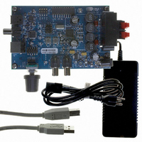
CRD4525-Q1
Description
REFERENCE BOARD FOR CS4525 PWM
Manufacturer
Cirrus Logic Inc
Series
Popguard®r
Specifications of CRD4525-Q1
Amplifier Type
Class D
Output Type
2-Channel (Stereo)
Max Output Power X Channels @ Load
15W x 2 @ 8 Ohm
Voltage - Supply
12 V ~ 18 V
Operating Temperature
0°C ~ 70°C
Board Type
Fully Populated
Utilized Ic / Part
CS4525
Lead Free Status / RoHS Status
Contains lead / RoHS non-compliant
Other names
598-1586


DS726PP3
6.1.8.5
Four channel mapping output configurations are supported for the PWM_SIG output pins as shown in
Table 10
tions. When disabled, the PWM_SIG pins will continuously drive a logic ‘0’ if the HiZPSig bit is set and will
be held in a high-impedance state if the HiZPSig bit is clear. The configurations are selected by the PW-
MDSel[1:0] bits in the Output Cfg register. The PWM_SIG2 can be configured to output the sub channel
even if the Bass Manager is not enabled; however, its signal will be muted unless the Bass Manager is
enabled by the BassMgr[2:0] bits. It should be noted that the HiZPSig bit must be set to enable the
PWM_SIG output drivers.
To allow stereo headphone operation when the PWM logic-level outputs are mapped in a non-stereo out-
put configuration, if the HP_DETECT/MUTE pin is configured for headphone detection (the HP/Mute bit
is set), the PWM logic-level output mapping can be affected by the active state of the headphone detection
input signal. See the
tion.
It should be noted that signal on channels 1, 2, and the sub channel are dependent upon the digital sound
processing blocks being used. For instance, if the 2-way crossover is enabled, channel 1 and 2 contain
the 2-way crossover channel A high- and low-pass outputs respectively. For more information, see the
Digital Sound Processing
Referenced Control
PWMDSel[1:0].....................
HiZPSig ...............................
HP/Mute ..............................
BassMgr[2:0] .......................
PWMDSel[1:0]
below. The configurations support stereo, channel 1 with sub, and channel 2 with sub applica-
00
01
10
11
PWM_SIG Logic-Level Output Configurations
Headphone Detection & Hardware Mute Input
Register Location
“PWM Signals Output Data Select (PWMDSel[1:0])” on page 73
“Hi-Z PWM_SIG Outputs (HiZPSig)” on page 79
“HP_Detect/Mute Pin Mode (HP/Mute)” on page 70
“Bass Cross-Over Frequency (BassMgr[2:0])” on page 79
Table 10. PWM Logic-Level Output Configurations
section and
PWM_SIG1
Channel 1
Channel 1
Channel 2
Disabled.
Figure 14 on page
29.
section on
Sub Channel
Sub Channel
PWM_SIG2
page 51
Channel 2
Disabled.
for more informa-
CS4525
49
Related parts for CRD4525-Q1
Image
Part Number
Description
Manufacturer
Datasheet
Request
R

Part Number:
Description:
Development Kit
Manufacturer:
Cirrus Logic Inc
Datasheet:
Part Number:
Description:
Development Kit
Manufacturer:
Cirrus Logic Inc
Datasheet:


Part Number:
Description:
High-efficiency PFC + Fluorescent Lamp Driver Reference Design
Manufacturer:
Cirrus Logic Inc
Datasheet:
Part Number:
Description:
Development Kit
Manufacturer:
Cirrus Logic Inc
Datasheet:
Part Number:
Description:
Development Kit
Manufacturer:
Cirrus Logic Inc
Datasheet:

Part Number:
Description:
Development Kit
Manufacturer:
Cirrus Logic Inc
Datasheet:
Part Number:
Description:
Development Kit
Manufacturer:
Cirrus Logic Inc
Datasheet:
Part Number:
Description:
Development Kit
Manufacturer:
Cirrus Logic Inc
Datasheet:
Part Number:
Description:
Audio Modules & Development Tools EvalBd 30W Qd Hlf- Brdg Dig Amp Pwr Stg
Manufacturer:
Cirrus Logic Inc
Datasheet:

Part Number:
Description:
EVALUATION BOARD FOR CS8427
Manufacturer:
Cirrus Logic Inc
Datasheet:

Part Number:
Description:
BOARD EVAL FOR CS8416 RCVR
Manufacturer:
Cirrus Logic Inc
Datasheet:

Part Number:
Description:
EVALUATION BOARD FOR CS8420
Manufacturer:
Cirrus Logic Inc
Datasheet:

Part Number:
Description:
KIT DEVELOPMENT EP9315 ARM9
Manufacturer:
Cirrus Logic Inc
Datasheet: