CRD4525-Q1 Cirrus Logic Inc, CRD4525-Q1 Datasheet - Page 72
CRD4525-Q1
Manufacturer Part Number
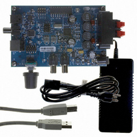
CRD4525-Q1
Description
REFERENCE BOARD FOR CS4525 PWM
Manufacturer
Cirrus Logic Inc
Series
Popguard®r
Specifications of CRD4525-Q1
Amplifier Type
Class D
Output Type
2-Channel (Stereo)
Max Output Power X Channels @ Load
15W x 2 @ 8 Ohm
Voltage - Supply
12 V ~ 18 V
Operating Temperature
0°C ~ 70°C
Board Type
Fully Populated
Utilized Ic / Part
CS4525
Lead Free Status / RoHS Status
Contains lead / RoHS non-compliant
Other names
598-1586


72
9.3
9.3.1
9.3.2
9.3.3
9.3.4
EnAuxPort
7
AUX Port Configuration (Address 03h)
Enable Aux Serial Port (EnAuxPort)
Default = 0
Function:
Controls the operation of the auxiliary serial port.
Delay & Warning Port Configuration (DlyPortCfg[1:0])
Default = 00
Function:
Controls the operation of the delay and warning port. See
page 44
Aux/Delay Serial Port Digital Interface Format (AuxI²S/LJ)
Default = 0
Function:
Selects the serial audio interface format for the data on AUX_SDOUT, DLY_SDIN, DLY_SDOUT. The re-
quired relationship between the Left/Right clock, serial clock and serial data is defined by the Digital In-
terface Format and the options are detailed in the
Aux Serial Port Right Channel Data Select (RChDSel[1:0])
Default = 01
Function:
Selects the data to be sent over the right channel of the auxiliary port serial data output signal.
EnAuxPort Setting
DlyPortCfg[1:0] Setting
AuxI²S/LJ Setting
RChDSel[1:0] Setting
0 .......................................... Auxiliary port disabled.
1 .......................................... Auxiliary port enabled.
00 ........................................ Port disabled.
01 ........................................ Port configured as serial audio delay interface.
10 ........................................ Port configured as an external thermal warning indicator for the foldback algorithm.
11......................................... Port disabled.
0 .......................................... Left-Justified, up to 24-bit.
1 .......................................... I²S, up to 24-bit.
00 ........................................ Channel A.
01 ........................................ Channel B.
10 ........................................ Sub Channel.
11......................................... Channel B crossover high-pass output.
DlyPortCfg1
for more information.
6
DlyPortCfg0
Auxiliary Port State
Delay Port Configuration
Auxiliary/Delay Port Serial Audio Interface Format
Aux Serial Port Right Channel Output Data Source
5
AuxI²S/LJ
4
RChDSel1
“Serial Audio Interfaces” on page
3
“Serial Audio Delay & Warning Input Port” on
RChDSel0
2
LChDSel1
1
62.
LChDSel0
CS4525
DS726PP3
0
Related parts for CRD4525-Q1
Image
Part Number
Description
Manufacturer
Datasheet
Request
R

Part Number:
Description:
Development Kit
Manufacturer:
Cirrus Logic Inc
Datasheet:
Part Number:
Description:
Development Kit
Manufacturer:
Cirrus Logic Inc
Datasheet:


Part Number:
Description:
High-efficiency PFC + Fluorescent Lamp Driver Reference Design
Manufacturer:
Cirrus Logic Inc
Datasheet:
Part Number:
Description:
Development Kit
Manufacturer:
Cirrus Logic Inc
Datasheet:
Part Number:
Description:
Development Kit
Manufacturer:
Cirrus Logic Inc
Datasheet:

Part Number:
Description:
Development Kit
Manufacturer:
Cirrus Logic Inc
Datasheet:
Part Number:
Description:
Development Kit
Manufacturer:
Cirrus Logic Inc
Datasheet:
Part Number:
Description:
Development Kit
Manufacturer:
Cirrus Logic Inc
Datasheet:
Part Number:
Description:
Audio Modules & Development Tools EvalBd 30W Qd Hlf- Brdg Dig Amp Pwr Stg
Manufacturer:
Cirrus Logic Inc
Datasheet:

Part Number:
Description:
EVALUATION BOARD FOR CS8427
Manufacturer:
Cirrus Logic Inc
Datasheet:

Part Number:
Description:
BOARD EVAL FOR CS8416 RCVR
Manufacturer:
Cirrus Logic Inc
Datasheet:

Part Number:
Description:
EVALUATION BOARD FOR CS8420
Manufacturer:
Cirrus Logic Inc
Datasheet:

Part Number:
Description:
KIT DEVELOPMENT EP9315 ARM9
Manufacturer:
Cirrus Logic Inc
Datasheet: