CRD4525-Q1 Cirrus Logic Inc, CRD4525-Q1 Datasheet - Page 55
CRD4525-Q1
Manufacturer Part Number
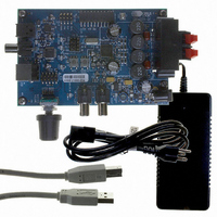
CRD4525-Q1
Description
REFERENCE BOARD FOR CS4525 PWM
Manufacturer
Cirrus Logic Inc
Series
Popguard®r
Specifications of CRD4525-Q1
Amplifier Type
Class D
Output Type
2-Channel (Stereo)
Max Output Power X Channels @ Load
15W x 2 @ 8 Ohm
Voltage - Supply
12 V ~ 18 V
Operating Temperature
0°C ~ 70°C
Board Type
Fully Populated
Utilized Ic / Part
CS4525
Lead Free Status / RoHS Status
Contains lead / RoHS non-compliant
Other names
598-1586


DS726PP3
6.2.3
6.2.4
6.2.2.2
1. Bring MUTE low to mute the device’s outputs and minimize audible pops.
2. Bring RST low to halt the operation of the device.
3. The SYS_CLK signal may now be removed. See
4. Remove power.
Input Source Selection
The CS4525 can accept analog or digital audio input signals. Digital audio input signals are supplied
through the serial audio input port as outlined in
signals are supplied through the internal ADC as outlined in
is selected by the ADC/SP pin as shown in
ing any audible pops or clicks.
In hardware mode, the serial audio input port supports both I²S and left-justified formats. The serial audio
interface format is selected by the I2S/LJ pin as shown in
PWM Channel Delay
In hardware mode, the CS4525 offsets the PWM switching edges between channels as a method of man-
aging switching noise and reducing radiated emissions.
The OUT3/OUT4 signal pair is delayed from the OUT1/OUT2 signal pair by 4 SYS_CLK cycles as shown
in
Figure 23
The device’s power consumption will be brought to an absolute minimum.
ADC/SP
I2S/LJ
High
High
Low
Low
Power-Down Sequence
below. The absolute delay time is calculated by multiplying the period SYS_CLK by 4.
Figure 23. Hardware Mode PWM Output Delay
OUT2
OUT1
OUT3
OUT4
Table 15. Serial Audio Interface Format Selection
Table 14. Input Source Selection
Table 14
Selected Serial Audio Interface Format
4 x T
“Serial Audio Interfaces” on page
Digital Audio Inputs (Serial Port)
Analog Audio Inputs (ADC)
SYS_CLK
Selected Input Source
below and can be changed at any time without caus-
section 6.2.1
Left-Justified
Table 15
“Analog Inputs” on page
I²S
on
below.
page 54
for more information.
62. Analog audio input
61. The input source
CS4525
55
Related parts for CRD4525-Q1
Image
Part Number
Description
Manufacturer
Datasheet
Request
R

Part Number:
Description:
Development Kit
Manufacturer:
Cirrus Logic Inc
Datasheet:
Part Number:
Description:
Development Kit
Manufacturer:
Cirrus Logic Inc
Datasheet:


Part Number:
Description:
High-efficiency PFC + Fluorescent Lamp Driver Reference Design
Manufacturer:
Cirrus Logic Inc
Datasheet:
Part Number:
Description:
Development Kit
Manufacturer:
Cirrus Logic Inc
Datasheet:
Part Number:
Description:
Development Kit
Manufacturer:
Cirrus Logic Inc
Datasheet:

Part Number:
Description:
Development Kit
Manufacturer:
Cirrus Logic Inc
Datasheet:
Part Number:
Description:
Development Kit
Manufacturer:
Cirrus Logic Inc
Datasheet:
Part Number:
Description:
Development Kit
Manufacturer:
Cirrus Logic Inc
Datasheet:
Part Number:
Description:
Audio Modules & Development Tools EvalBd 30W Qd Hlf- Brdg Dig Amp Pwr Stg
Manufacturer:
Cirrus Logic Inc
Datasheet:

Part Number:
Description:
EVALUATION BOARD FOR CS8427
Manufacturer:
Cirrus Logic Inc
Datasheet:

Part Number:
Description:
BOARD EVAL FOR CS8416 RCVR
Manufacturer:
Cirrus Logic Inc
Datasheet:

Part Number:
Description:
EVALUATION BOARD FOR CS8420
Manufacturer:
Cirrus Logic Inc
Datasheet:

Part Number:
Description:
KIT DEVELOPMENT EP9315 ARM9
Manufacturer:
Cirrus Logic Inc
Datasheet: