CRD4525-Q1 Cirrus Logic Inc, CRD4525-Q1 Datasheet - Page 61
CRD4525-Q1
Manufacturer Part Number
CRD4525-Q1
Description
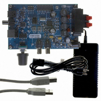
REFERENCE BOARD FOR CS4525 PWM
Manufacturer
Cirrus Logic Inc
Series
Popguard®r
Specifications of CRD4525-Q1
Amplifier Type
Class D
Output Type
2-Channel (Stereo)
Max Output Power X Channels @ Load
15W x 2 @ 8 Ohm
Voltage - Supply
12 V ~ 18 V
Operating Temperature
0°C ~ 70°C
Board Type
Fully Populated
Utilized Ic / Part
CS4525
Lead Free Status / RoHS Status
Contains lead / RoHS non-compliant
Other names
598-1586


DS726PP3
6.5
Analog Inputs
Very few components are required to interface between the audio source and the CS4525’s analog inputs,
AINL and AINR. A single order passive low-pass filter is recommended to prevent high-frequency content
from aliasing into the audio band due to the analog-to-digital conversion process. Also, a DC-blocking ca-
pacitor is required as the CS4525’s analog inputs are internally biased to VQ.
The recommended analog input circuit is shown in
ages as defined in the
high-frequency filtering with a first-order passive low-pass filter that has less than 0.05 dB of attenuation at
24 kHz. It also includes a DC blocking capacitor to accommodate the analog input pins’ bias level.
To interface 2 V
Figure 29
to condition the input signal for the CS4525’s full-scale input voltage, a first-order passive low-pass filter that
has less than 0.05 dB of attenuation at 24 kHz, and a DC blocking capacitor to accommodate for the analog
input pins’ bias level. The passive attenuator network should be placed as close as possible to the CS4525’s
analog input pins to reduce the potential for noise and signal coupling into the analog input traces.
It should be noted that the external DC blocking capacitor forms a high-pass filter with the CS4525’s input
impedance. Both filters shown above have less than 0.2 dB attenuation at 20 Hz due to this effect. Increas-
ing the value of this capacitor will lower this high-pass corner frequency, and decreasing it’s value will in-
crease the corner frequency.
shows the recommended input circuit for 2 V
RMS
input signals with the CS4525’s analog inputs, an external resistor divider is required.
Right Input
Right Input
Left Input
Analog Input Characteristics
Left Input
Figure 28. Recommended Unity Gain Input Filter
Figure 29. Recommended 2 V
100 kΩ
100 kΩ
8.06 kΩ
8.06 kΩ
5.62 kΩ
5.62 kΩ
1 µF
1 µF
Figure 28
table on
365 Ω
365 Ω
1 µF
1 µF
RMS
1800 pF
1800 pF
100 pF
100 pF
C0G
C0G
C0G
C0G
inputs. It includes a -8.4 dB passive attenuator
RMS
below will accommodate full-scale input volt-
page
Input Filter
19. This circuit provides the necessary
AINL
AINR
AINL
AINR
CS4525
CS4525
CS4525
61
Related parts for CRD4525-Q1
Image
Part Number
Description
Manufacturer
Datasheet
Request
R

Part Number:
Description:
Development Kit
Manufacturer:
Cirrus Logic Inc
Datasheet:
Part Number:
Description:
Development Kit
Manufacturer:
Cirrus Logic Inc
Datasheet:


Part Number:
Description:
High-efficiency PFC + Fluorescent Lamp Driver Reference Design
Manufacturer:
Cirrus Logic Inc
Datasheet:
Part Number:
Description:
Development Kit
Manufacturer:
Cirrus Logic Inc
Datasheet:
Part Number:
Description:
Development Kit
Manufacturer:
Cirrus Logic Inc
Datasheet:

Part Number:
Description:
Development Kit
Manufacturer:
Cirrus Logic Inc
Datasheet:
Part Number:
Description:
Development Kit
Manufacturer:
Cirrus Logic Inc
Datasheet:
Part Number:
Description:
Development Kit
Manufacturer:
Cirrus Logic Inc
Datasheet:
Part Number:
Description:
Audio Modules & Development Tools EvalBd 30W Qd Hlf- Brdg Dig Amp Pwr Stg
Manufacturer:
Cirrus Logic Inc
Datasheet:

Part Number:
Description:
EVALUATION BOARD FOR CS8427
Manufacturer:
Cirrus Logic Inc
Datasheet:

Part Number:
Description:
BOARD EVAL FOR CS8416 RCVR
Manufacturer:
Cirrus Logic Inc
Datasheet:

Part Number:
Description:
EVALUATION BOARD FOR CS8420
Manufacturer:
Cirrus Logic Inc
Datasheet:

Part Number:
Description:
KIT DEVELOPMENT EP9315 ARM9
Manufacturer:
Cirrus Logic Inc
Datasheet: