CRD4525-Q1 Cirrus Logic Inc, CRD4525-Q1 Datasheet - Page 39
CRD4525-Q1
Manufacturer Part Number
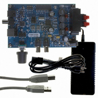
CRD4525-Q1
Description
REFERENCE BOARD FOR CS4525 PWM
Manufacturer
Cirrus Logic Inc
Series
Popguard®r
Specifications of CRD4525-Q1
Amplifier Type
Class D
Output Type
2-Channel (Stereo)
Max Output Power X Channels @ Load
15W x 2 @ 8 Ohm
Voltage - Supply
12 V ~ 18 V
Operating Temperature
0°C ~ 70°C
Board Type
Fully Populated
Utilized Ic / Part
CS4525
Lead Free Status / RoHS Status
Contains lead / RoHS non-compliant
Other names
598-1586


DS726PP3
6.1.4.11 Thermal Limiter
The CS4525 implements a thermal limiter function to provide a quick corrective response to potentially
damaging thermal overload conditions. The thermal limiter feature operates by sensing the presence of
a thermal warning condition and, in response, utilizes the peak signal limiter to dynamically limit the signal
amplitude prior to the PWM modulators. This effectively limits the output power capability of the device,
thereby allowing the temperature to reduce to acceptable levels without fully interrupting operation.
The thermal limiter is enabled by the EnThLim bit in the Limiter Configuration 3 register. When enabled,
the thermal limiter will trigger once when either of the following conditions is met:
1. The junction temperature crosses the thermal warning threshold for the first time after the thermal
2. The junction temperature is greater than the thermal warning threshold at the time the thermal limiter
Once triggered, the thermal limiter will remain in a triggered state until the RST pin is driven low.
When in the triggered state, the thermal limiter will engage whenever the EnThLim bit is set. While en-
gaged, the thermal limiter utilizes the peak signal limiter function to dynamically limit the signal amplitude
prior to the PWM modulators via the peak signal limiter; the characteristics of this limiting function are de-
scribed in
abled via the EnLimiter bit, the peak signal limiter will be automatically enabled and its minimum and
maximum thresholds will be set to -3 dB. If the thermal limiter is engaged and the peak signal limiter is
enabled, an additional -3dB will be automatically applied to the minimum and maximum thresholds estab-
lished in the Limiter Cfg 1 register. The automatic enabling of the peak signal limiter and the automatic
application of additional attenuation to its thresholds is done internal to the CS4245; the values of the En-
Limiter, Min[2:0], and Max[2:0] bits in the Limiter Cfg 1 register are not affected by the engagement of the
thermal limiter function.
It should be noted that the thermal limiter can only be triggered once following the release of the RST sig-
nal. Once it has triggered, the thermal limiter’s attenuation will always be implemented while the thermal
limiter is enabled. If the thermal limiter is disabled after it has triggered, the internal enabling of the peak
signal limiter and the additional -3 dB attenuation applied to its minimum and maximum thresholds will be
released. In this state, the peak signal limiter’s operation will follow the EnLimiter, Min[2:0], and Max[2:0]
bits with no internal modification. If EnThLim is set again before the CS4525 has been reset (by toggling
the RST pin low and then high), thermal limiting will engage immediately.
Referenced Control
EnThLim..............................
EnLimiter .............................
Max[2:0] ..............................
Min[2:0] ...............................
limiter function is enabled.
function is enabled.
Section 6.1.4.10
Register Location
“Enable Thermal Limiter (EnThLim)” on page 87
“Peak Detect and Limiter Enable (EnLimiter)” on page 86
“Maximum Threshold (Max[2:0])” on page 85
“Minimum Threshold (Min[2:0])” on page 85
on
page
37. If the thermal limiter is engaged and the peak signal limiter is dis-
CS4525
39
Related parts for CRD4525-Q1
Image
Part Number
Description
Manufacturer
Datasheet
Request
R

Part Number:
Description:
Development Kit
Manufacturer:
Cirrus Logic Inc
Datasheet:
Part Number:
Description:
Development Kit
Manufacturer:
Cirrus Logic Inc
Datasheet:


Part Number:
Description:
High-efficiency PFC + Fluorescent Lamp Driver Reference Design
Manufacturer:
Cirrus Logic Inc
Datasheet:
Part Number:
Description:
Development Kit
Manufacturer:
Cirrus Logic Inc
Datasheet:
Part Number:
Description:
Development Kit
Manufacturer:
Cirrus Logic Inc
Datasheet:

Part Number:
Description:
Development Kit
Manufacturer:
Cirrus Logic Inc
Datasheet:
Part Number:
Description:
Development Kit
Manufacturer:
Cirrus Logic Inc
Datasheet:
Part Number:
Description:
Development Kit
Manufacturer:
Cirrus Logic Inc
Datasheet:
Part Number:
Description:
Audio Modules & Development Tools EvalBd 30W Qd Hlf- Brdg Dig Amp Pwr Stg
Manufacturer:
Cirrus Logic Inc
Datasheet:

Part Number:
Description:
EVALUATION BOARD FOR CS8427
Manufacturer:
Cirrus Logic Inc
Datasheet:

Part Number:
Description:
BOARD EVAL FOR CS8416 RCVR
Manufacturer:
Cirrus Logic Inc
Datasheet:

Part Number:
Description:
EVALUATION BOARD FOR CS8420
Manufacturer:
Cirrus Logic Inc
Datasheet:

Part Number:
Description:
KIT DEVELOPMENT EP9315 ARM9
Manufacturer:
Cirrus Logic Inc
Datasheet: