CRD4525-Q1 Cirrus Logic Inc, CRD4525-Q1 Datasheet - Page 30
CRD4525-Q1
Manufacturer Part Number
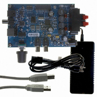
CRD4525-Q1
Description
REFERENCE BOARD FOR CS4525 PWM
Manufacturer
Cirrus Logic Inc
Series
Popguard®r
Specifications of CRD4525-Q1
Amplifier Type
Class D
Output Type
2-Channel (Stereo)
Max Output Power X Channels @ Load
15W x 2 @ 8 Ohm
Voltage - Supply
12 V ~ 18 V
Operating Temperature
0°C ~ 70°C
Board Type
Fully Populated
Utilized Ic / Part
CS4525
Lead Free Status / RoHS Status
Contains lead / RoHS non-compliant
Other names
598-1586


30
6.1.4.1
Applying any gain to a full-scale signal in the digital domain will cause the signal to clip. To prevent this,
a pre-scaler block is included prior to the internal digital signal processing blocks. This allows the input
signal to be attenuated before processing to ensure that any signal boosting, such as gain in a shelving
filter, will not cause a channel to clip.
The pre-scaler block allows up to -14.0 dB of attenuation in 2.0 dB increments and is controlled with the
PreScale[2:0] bits.
6.1.4.2
The CS4525 includes a high-pass filter at the beginning of the digital signal processing chain to remove
any DC content from the input signal prior to the remaining internal digital signal processing blocks. The
high-pass filter operates by continuously subtracting a measure of the DC offset from the input signal and
may be used regardless of the input data source.
The digital signal processing high-pass filter can be disabled by clearing the EnDigHPF bit.
6.1.4.3
The CS4525 implements independent channel mixers to provide for both mono mixes and channel swaps
for the left and right channels. The channel mixers are controlled by the LChMix[1:0] and RChMix[1:0] bits
in the Mixer Config register.
To allow stereo operation when a mono mix is configured, when the HP_DETECT/MUTE pin is configured
for headphone detection (the HP/Mute bit is set), the operation of the left channel mixer is affected by the
active state of the headphone detection input signal. In this configuration, when the left channel mixer is
configured for a mono mix (LChMix[1:0] = 01 or 10) and the headphone detection input signal becomes
active, the left channel mixer will be automatically reconfigured to output the left channel, thereby dis-
abling the mono mix. When the headphone detection input signal becomes inactive, the mixer will be au-
tomatically reconfigured to operate as dictated by the LChMix[1:0] bits.
It should be noted that the right channel mixer output is unaffected by the headphone detection input sig-
nal and will always operate as dictated by the RChMix[1:0] bits.
Referenced Control
PreScale[2:0].......................
Referenced Control
EnDigHPF ...........................
Referenced Control
LChMix[1:0] .........................
RChMix[1:0] ........................
HP/Mute ..............................
Pre-Scaler
Digital Signal Processing High-Pass Filter
Channel Mixer
Register Location
Register Location
Register Location
“Pre-Scale Attenuation (PreScale[2:0])” on page 75
“Digital Signal Processing High-Pass Filter (EnDigHPF)” on page 77
“Left Channel Mixer (LChMix[1:0])” on page 76
“Right Channel Mixer (RChMix[1:0])” on page 76
“HP_Detect/Mute Pin Mode (HP/Mute)” on page 70
CS4525
DS726PP3
Related parts for CRD4525-Q1
Image
Part Number
Description
Manufacturer
Datasheet
Request
R

Part Number:
Description:
Development Kit
Manufacturer:
Cirrus Logic Inc
Datasheet:
Part Number:
Description:
Development Kit
Manufacturer:
Cirrus Logic Inc
Datasheet:


Part Number:
Description:
High-efficiency PFC + Fluorescent Lamp Driver Reference Design
Manufacturer:
Cirrus Logic Inc
Datasheet:
Part Number:
Description:
Development Kit
Manufacturer:
Cirrus Logic Inc
Datasheet:
Part Number:
Description:
Development Kit
Manufacturer:
Cirrus Logic Inc
Datasheet:

Part Number:
Description:
Development Kit
Manufacturer:
Cirrus Logic Inc
Datasheet:
Part Number:
Description:
Development Kit
Manufacturer:
Cirrus Logic Inc
Datasheet:
Part Number:
Description:
Development Kit
Manufacturer:
Cirrus Logic Inc
Datasheet:
Part Number:
Description:
Audio Modules & Development Tools EvalBd 30W Qd Hlf- Brdg Dig Amp Pwr Stg
Manufacturer:
Cirrus Logic Inc
Datasheet:

Part Number:
Description:
EVALUATION BOARD FOR CS8427
Manufacturer:
Cirrus Logic Inc
Datasheet:

Part Number:
Description:
BOARD EVAL FOR CS8416 RCVR
Manufacturer:
Cirrus Logic Inc
Datasheet:

Part Number:
Description:
EVALUATION BOARD FOR CS8420
Manufacturer:
Cirrus Logic Inc
Datasheet:

Part Number:
Description:
KIT DEVELOPMENT EP9315 ARM9
Manufacturer:
Cirrus Logic Inc
Datasheet: