STEVAL-IFS012V1 STMicroelectronics, STEVAL-IFS012V1 Datasheet - Page 103
STEVAL-IFS012V1
Manufacturer Part Number
STEVAL-IFS012V1
Description
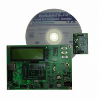
BOARD ST72651AR6/STTS75/STLM20
Manufacturer
STMicroelectronics
Specifications of STEVAL-IFS012V1
Sensor Type
Temperature
Sensing Range
Depends on IC
Interface
I²C, USB
Sensitivity
Depends on IC
Voltage - Supply
5V
Embedded
Yes, MCU, 8-Bit
Utilized Ic / Part
ST72F651AR6, STTS75, STLM20
Lead Free Status / RoHS Status
Lead free / RoHS Compliant
Other names
497-8419
Available stocks
Company
Part Number
Manufacturer
Quantity
Price


SERIAL PERIPHERAL INTERFACE (Cont’d)
CONTROL/STATUS REGISTER (SPICSR)
Read/Write (some bits Read Only)
Reset Value: 0000 0000 (00h)
Bit 7 = SPIF Serial Peripheral Data Transfer Flag
0: Data transfer is in progress or the flag has been
1: Data transfer between the device and an exter-
Note: While the SPIF bit is set, all writes to the
SPIDR register are inhibited until the SPICSR reg-
ister is read.
Bit 6 = WCOL Write Collision status (Read only).
This bit is set by hardware when a write to the
SPIDR register is done during a transmit se-
quence. It is cleared by a software sequence (see
Figure
0: No write collision occurred
1: A write collision has been detected
Bit 5 = OVR SPI Overrun error (Read only).
This bit is set by hardware when the byte currently
being received in the shift register is ready to be
transferred into the SPIDR register while SPIF = 1
(See
SPIE = 1 in SPICR register. The OVR bit is cleared
by software reading the SPICSR register.
0: No overrun error
1: Overrun error detected
Bit 4 = MODF Mode Fault flag (Read only).
This bit is set by hardware when the SS pin is
pulled low in master mode (see
Master Mode Fault
be generated if SPIE=1 in the SPICR register. This
bit is cleared by a software sequence (An access
to the SPICSR register while MODF=1 followed by
a write to the SPICR register).
0: No master mode fault detected
1: A fault in master mode has been detected
Bit 3 = Reserved, must be kept cleared.
SPIF
cleared.
nal device has been completed.
(Read only).
This bit is set by hardware when a transfer has
been completed. An interrupt is generated if
SPIE=1 in the SPICR register. It is cleared by a
software sequence (an access to the SPICSR
register followed by a write or a read to the
SPIDR register).
7
Section
60).
WCOL
11.6.5.2). An interrupt is generated if
OVR
(MODF)). An SPI interrupt can
MODF
-
Section 11.6.5.1
SOD
SSM
Doc ID 7215 Rev 4
SSI
0
Bit 2 = SOD SPI Output Disable.
This bit is set and cleared by software. When set, it
disables the alternate function of the SPI output
(MOSI in master mode / MISO in slave mode)
0: SPI output enabled (if SPE=1)
1: SPI output disabled
Bit 1 = SSM SS Management.
This bit is set and cleared by software. When set, it
disables the alternate function of the SPI SS pin
and uses the SSI bit value instead. See
11.6.3.2 Slave Select
0: Hardware management (SS managed by exter-
1: Software management (internal SS signal con-
Bit 0 = SSI SS Internal Mode.
This bit is set and cleared by software. It acts as a
‘chip select’ by controlling the level of the SS slave
select signal when the SSM bit is set.
0: Slave selected
1: Slave deselected
DATA I/O REGISTER (SPIDR)
Read/Write
Reset Value: Undefined
The SPIDR register is used to transmit and receive
data on the serial bus. In a master device, a write
to this register will initiate transmission/reception
of another byte.
Notes: During the last clock cycle the SPIF bit is
set, a copy of the received data byte in the shift
register is moved to a buffer. When the user reads
the serial peripheral data I/O register, the buffer is
actually being read.
While the SPIF bit is set, all writes to the SPIDR
register are inhibited until the SPICSR register is
read.
Warning: A write to the SPIDR register places
data directly into the shift register for transmission.
A read to the SPIDR register returns the value lo-
cated in the buffer and not the content of the shift
register (see
D7
nal pin)
trolled by SSI bit. External SS pin free for gener-
al-purpose I/O)
7
D6
Figure
D5
55).
D4
Management.
D3
D2
ST72651AR6
D1
Section
103/161
D0
0
Related parts for STEVAL-IFS012V1
Image
Part Number
Description
Manufacturer
Datasheet
Request
R

Part Number:
Description:
BOARD EVAL SPZB260 MOD FOR STR9
Manufacturer:
STMicroelectronics
Datasheet:

Part Number:
Description:
BOARD EVAL EXTENSION SN250
Manufacturer:
STMicroelectronics
Datasheet:

Part Number:
Description:
BOARD EVAL AB-54003L-512
Manufacturer:
STMicroelectronics
Datasheet:

Part Number:
Description:
BOARD REF DESIGN RF DMOS PWR AMP
Manufacturer:
STMicroelectronics
Datasheet:

Part Number:
Description:
BOARD EVAL PWR AMP AB-84008L-470
Manufacturer:
STMicroelectronics
Datasheet:

Part Number:
Description:
BOARD EVAL FOR STM32F103XX
Manufacturer:
STMicroelectronics
Datasheet:

Part Number:
Description:
BOARD EVAL AB-54003L-512
Manufacturer:
STMicroelectronics
Datasheet:

Part Number:
Description:
BOARD SMART PLUG STM32 SPZB260PR
Manufacturer:
STMicroelectronics
Datasheet:

Part Number:
Description:
BOARD DEMO BLUETOOTH SPBT2532C2
Manufacturer:
STMicroelectronics
Datasheet:
Part Number:
Description:
ZIGBEE USB DONGLE EVAL KIT
Manufacturer:
STMicroelectronics
Datasheet:
Part Number:
Description:
STMicroelectronics [RIPPLE-CARRY BINARY COUNTER/DIVIDERS]
Manufacturer:
STMicroelectronics
Datasheet:
Part Number:
Description:
STMicroelectronics [LIQUID-CRYSTAL DISPLAY DRIVERS]
Manufacturer:
STMicroelectronics
Datasheet:

Part Number:
Description:
BOARD EVAL FOR MEMS SENSORS
Manufacturer:
STMicroelectronics
Datasheet: