STEVAL-IFS012V1 STMicroelectronics, STEVAL-IFS012V1 Datasheet - Page 58
STEVAL-IFS012V1
Manufacturer Part Number
STEVAL-IFS012V1
Description
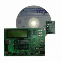
BOARD ST72651AR6/STTS75/STLM20
Manufacturer
STMicroelectronics
Specifications of STEVAL-IFS012V1
Sensor Type
Temperature
Sensing Range
Depends on IC
Interface
I²C, USB
Sensitivity
Depends on IC
Voltage - Supply
5V
Embedded
Yes, MCU, 8-Bit
Utilized Ic / Part
ST72F651AR6, STTS75, STLM20
Lead Free Status / RoHS Status
Lead free / RoHS Compliant
Other names
497-8419
Available stocks
Company
Part Number
Manufacturer
Quantity
Price


ST72651AR6
Data Transfer Coprocessor (Cont’d)
When the USB interface is used, data transfer is
typically controlled by a host computer.
The ST7 core can also read from and write to the
data buffer of the DTC. Typically, the ST7 controls
the application when the USB not used (autono-
mous mode). The buffer can potentially be ac-
cessed by any one of three requestors, the ST7,
the DTC and the USB. Mastership of the buffer is
not time limited. While a master is accessing the
buffer, other requests will not be acknowledged
until the buffer is freed by the master. If several re-
quests are pending, when the buffer is free it is
granted to the source with the highest priority in
the daisy-chain (fixed by hardware), first the ST7,
secondly the USB and finally the DTC.
Note: Any access by the ST7 to the buffer requires
more cycles than either a DTC or USB access. For
performance reasons, when the USB interface is
exchanging data with the DTC, ST7 accesses
should be avoided if possible.
11.2.3 Loading the Protocol Software
The DTC must first be initialized by loading the
protocol-specific software plug-in (provided by ST-
Microelectronics) into the DTC RAM. To do this:
1. Stop the DTC by clearing the RUN bit in the
2. Remove the write protection by setting the
3. Load the (null-terminated) software plug-in in
Figure 35. State Diagram of DTC Operations
58/161
1
DTCCR register
LOAD bit in the DTCCR register
the DTC RAM.
DTC RAM
LOAD=1
LOAD
RUN=0
INIT=0
POINTER
CHANGE
LOAD=0
RUN=0
INIT=1
LOAD=1
INIT=1
LOAD=0
INIT=0
DTC
IDLE
LOAD=0
RUN=0
INIT=0
Doc ID 7215 Rev 4
RUN=0
RUN=1
4. Restore the write protection by clearing the
The DTC is then ready for operation.
11.2.4 Executing the Protocol Functions
To execute any of the software plug-in functions
follow the procedure below:
1. Clear the RUN bit to stop the DTC
2. Select the function by writing its address in the
3. Set the INIT bit in the DTCCR register to copy
4. Clear the INIT bit to return to idle state.
5. Set the RUN bit to start the DTC.
11.2.5 Changing the DTCPR pointer on the fly
As shown in
by writing INIT=1 while the DTC is running
(RUN=1), however if the DTC is executing an in-
ternal interrupt routine, there will be a delay until
interrupt handling is completed.
11.2.6 Low Power Modes
Mode
WAIT
HALT
INIT=0
LOAD bit in the DTCCR register
DTCPR register (refer to the separate docu-
ment for address information).
the DTCPR pointer to the DTC.
ON-THE-FLY
RUNNING
LOAD=0
RUN=1
POINTER
CHANGE
INIT=0
DTC
LOAD=0
RUN=1
INIT=1
Description
No effect on DTC
DTC halted.
Figure
INIT=1
35, the pointer can be changed
Related parts for STEVAL-IFS012V1
Image
Part Number
Description
Manufacturer
Datasheet
Request
R

Part Number:
Description:
BOARD EVAL SPZB260 MOD FOR STR9
Manufacturer:
STMicroelectronics
Datasheet:

Part Number:
Description:
BOARD EVAL EXTENSION SN250
Manufacturer:
STMicroelectronics
Datasheet:

Part Number:
Description:
BOARD EVAL AB-54003L-512
Manufacturer:
STMicroelectronics
Datasheet:

Part Number:
Description:
BOARD REF DESIGN RF DMOS PWR AMP
Manufacturer:
STMicroelectronics
Datasheet:

Part Number:
Description:
BOARD EVAL PWR AMP AB-84008L-470
Manufacturer:
STMicroelectronics
Datasheet:

Part Number:
Description:
BOARD EVAL FOR STM32F103XX
Manufacturer:
STMicroelectronics
Datasheet:

Part Number:
Description:
BOARD EVAL AB-54003L-512
Manufacturer:
STMicroelectronics
Datasheet:

Part Number:
Description:
BOARD SMART PLUG STM32 SPZB260PR
Manufacturer:
STMicroelectronics
Datasheet:

Part Number:
Description:
BOARD DEMO BLUETOOTH SPBT2532C2
Manufacturer:
STMicroelectronics
Datasheet:
Part Number:
Description:
ZIGBEE USB DONGLE EVAL KIT
Manufacturer:
STMicroelectronics
Datasheet:
Part Number:
Description:
STMicroelectronics [RIPPLE-CARRY BINARY COUNTER/DIVIDERS]
Manufacturer:
STMicroelectronics
Datasheet:
Part Number:
Description:
STMicroelectronics [LIQUID-CRYSTAL DISPLAY DRIVERS]
Manufacturer:
STMicroelectronics
Datasheet:

Part Number:
Description:
BOARD EVAL FOR MEMS SENSORS
Manufacturer:
STMicroelectronics
Datasheet: