STEVAL-IFS012V1 STMicroelectronics, STEVAL-IFS012V1 Datasheet - Page 46
STEVAL-IFS012V1
Manufacturer Part Number
STEVAL-IFS012V1
Description
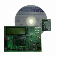
BOARD ST72651AR6/STTS75/STLM20
Manufacturer
STMicroelectronics
Specifications of STEVAL-IFS012V1
Sensor Type
Temperature
Sensing Range
Depends on IC
Interface
I²C, USB
Sensitivity
Depends on IC
Voltage - Supply
5V
Embedded
Yes, MCU, 8-Bit
Utilized Ic / Part
ST72F651AR6, STTS75, STLM20
Lead Free Status / RoHS Status
Lead free / RoHS Compliant
Other names
497-8419
Available stocks
Company
Part Number
Manufacturer
Quantity
Price


ST72651AR6
I/O PORTS (Cont’d)
9.2.2 Output Modes
Two different output modes can be selected by
software through the OR register: Output push-pull
and open-drain.
DR register value and output pin status:
The output configuration is selected by setting the
corresponding DDR register bit. In this case, writ-
ing the DR register applies this digital value to the
I/O pin through the latch. Reading the DR register
returns the digital value present on the external I/O
pin. Consequently even in output mode a value
written to an open drain port may differ from the
value read from the port. For example, if software
writes a ‘1’ in the latch, this value will be applied to
the pin, but the pin may stay at ‘0’ depending on
the state of the external circuitry. For this reason,
bit manipulation even using instructions like BRES
and BSET must not be used on open drain ports
as they work by reading a byte, changing a bit and
writing back a byte. A workaround for applications
requiring bit manipulation on Open Drain I/Os is
given in
9.2.3 Alternate Functions
When an on-chip peripheral is configured to use a
pin, the alternate function is automatically select-
ed. This alternate function takes priority over the
standard I/O programming.
When the signal comes from an on-chip peripher-
al, the I/O pin is automatically configured in output
mode (push-pull or open drain according to the pe-
ripheral).
When the signal goes to an on-chip peripheral, the
I/O pin must be configured in input mode. In this
46/161
1
DR
0
1
Section
Push-pull
9.2.5.
V
V
DD
SS
Open-drain
Floating
Vss
Doc ID 7215 Rev 4
case, the pin state is also digitally readable by ad-
dressing the DR register.
Note: Input pull-up configuration can cause unex-
pected values at the input of the alternate periph-
eral input. When an on-chip peripheral uses a pin
as input and output, this pin has to be configured
in input floating mode.
CAUTION: The alternate function must not be ac-
tivated as long as the pin is configured as input
with interrupt, in order to avoid generating spurious
interrupts.
Analog alternate function
When the pin is used as an ADC input, the I/O
must be configured as floating input. The analog
multiplexer (controlled by the ADC registers)
switches the analog voltage present on the select-
ed pin to the common analog rail which is connect-
ed to the ADC input.
It is recommended not to change the voltage level
or loading on any port pin while conversion is in
progress. Furthermore it is recommended not to
have clocking pins located close to a selected an-
alog pin.
WARNING: The analog input voltage level must
be within the limits stated in the absolute maxi-
mum ratings.
9.2.4 V
The microcontroller is able to power the I/O pins
from a specific supply rail connected to the V
pin.
If V
be used and are tied to ground. Furthermore, this
is also true in an application where the internal
regulator is used but not yet enabled (this is at
least the case during the reset stage).
DDF
DDF
is not present, all V
-Powered I/Os
DDF
-driven I/Os cannot
DDF
Related parts for STEVAL-IFS012V1
Image
Part Number
Description
Manufacturer
Datasheet
Request
R

Part Number:
Description:
BOARD EVAL SPZB260 MOD FOR STR9
Manufacturer:
STMicroelectronics
Datasheet:

Part Number:
Description:
BOARD EVAL EXTENSION SN250
Manufacturer:
STMicroelectronics
Datasheet:

Part Number:
Description:
BOARD EVAL AB-54003L-512
Manufacturer:
STMicroelectronics
Datasheet:

Part Number:
Description:
BOARD REF DESIGN RF DMOS PWR AMP
Manufacturer:
STMicroelectronics
Datasheet:

Part Number:
Description:
BOARD EVAL PWR AMP AB-84008L-470
Manufacturer:
STMicroelectronics
Datasheet:

Part Number:
Description:
BOARD EVAL FOR STM32F103XX
Manufacturer:
STMicroelectronics
Datasheet:

Part Number:
Description:
BOARD EVAL AB-54003L-512
Manufacturer:
STMicroelectronics
Datasheet:

Part Number:
Description:
BOARD SMART PLUG STM32 SPZB260PR
Manufacturer:
STMicroelectronics
Datasheet:

Part Number:
Description:
BOARD DEMO BLUETOOTH SPBT2532C2
Manufacturer:
STMicroelectronics
Datasheet:
Part Number:
Description:
ZIGBEE USB DONGLE EVAL KIT
Manufacturer:
STMicroelectronics
Datasheet:
Part Number:
Description:
STMicroelectronics [RIPPLE-CARRY BINARY COUNTER/DIVIDERS]
Manufacturer:
STMicroelectronics
Datasheet:
Part Number:
Description:
STMicroelectronics [LIQUID-CRYSTAL DISPLAY DRIVERS]
Manufacturer:
STMicroelectronics
Datasheet:

Part Number:
Description:
BOARD EVAL FOR MEMS SENSORS
Manufacturer:
STMicroelectronics
Datasheet: