STEVAL-IFS012V1 STMicroelectronics, STEVAL-IFS012V1 Datasheet - Page 44
STEVAL-IFS012V1
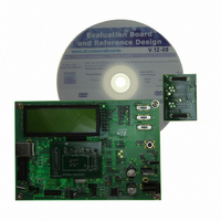
Manufacturer Part Number
STEVAL-IFS012V1
Description
BOARD ST72651AR6/STTS75/STLM20
Manufacturer
STMicroelectronics
Specifications of STEVAL-IFS012V1
Sensor Type
Temperature
Sensing Range
Depends on IC
Interface
I²C, USB
Sensitivity
Depends on IC
Voltage - Supply
5V
Embedded
Yes, MCU, 8-Bit
Utilized Ic / Part
ST72F651AR6, STTS75, STLM20
Lead Free Status / RoHS Status
Lead free / RoHS Compliant
Other names
497-8419
Available stocks
Company
Part Number
Manufacturer
Quantity
Price


ST72651AR6
POWER SAVING MODES (Cont’d)
8.3 HALT MODE
The HALT mode is the MCU lowest power con-
sumption mode. The HALT mode is entered by ex-
ecuting the HALT instruction. The internal oscilla-
tor is then turned off, causing all internal process-
ing to be stopped, including the operation of the
on-chip peripherals.
When entering HALT mode, the
Condition Code Register are cleared. Thus, any of
the external interrupts (ITi or USB end suspend
mode), are allowed and if an interrupt occurs, the
CPU clock becomes active.
The MCU can exit HALT mode on reception of ei-
ther an external interrupt on ITi, a plug/unplug in-
terrupt, an end suspend mode interrupt coming
from USB peripheral, an SPI interrupt or a reset.
The oscillator is then turned on and a stabilization
time is provided before releasing CPU operation.
The stabilization time is 512 CPU clock cycles.
After the start up delay, the CPU continues opera-
tion by servicing the interrupt which wakes it up or
by fetching the reset vector if a reset wakes it up.
Related Documentation
AN980: ST7 Keypad Decoding Techniques, Im-
plementing Wake-Up on Keystroke
AN1014: How to Minimize the ST7 Power Con-
sumption
AN1605: Using an active RC to wakeup the
ST7LITE0 from power saving mode
44/161
1
I[1:0] bits
Doc ID 7215 Rev 4
in the
Figure 30. HALT Mode Flow Chart
Note: Before servicing an interrupt, the CC
register is pushed on the stack. The
set during the interrupt routine and cleared
when the CC register is popped.
N
INTERRUPT*
EXTERNAL
Y
OSCILLATOR
PERIPH. CLOCK
CPU CLOCK
I1:0] BITS
OSCILLATOR
PERIPH. CLOCK
CPU CLOCK
OR SERVICE INTERRUPT
I1:0] BITS
FETCH RESET VECTOR
(Refer to
N
HALT INSTRUCTION
Figure
DELAY
Figure 19
RESET
20)
Y
I1:0] bits
OFF
OFF
OFF
CLEARED
and
ON
ON
ON
SET
are
Related parts for STEVAL-IFS012V1
Image
Part Number
Description
Manufacturer
Datasheet
Request
R

Part Number:
Description:
BOARD EVAL SPZB260 MOD FOR STR9
Manufacturer:
STMicroelectronics
Datasheet:

Part Number:
Description:
BOARD EVAL EXTENSION SN250
Manufacturer:
STMicroelectronics
Datasheet:

Part Number:
Description:
BOARD EVAL AB-54003L-512
Manufacturer:
STMicroelectronics
Datasheet:

Part Number:
Description:
BOARD REF DESIGN RF DMOS PWR AMP
Manufacturer:
STMicroelectronics
Datasheet:

Part Number:
Description:
BOARD EVAL PWR AMP AB-84008L-470
Manufacturer:
STMicroelectronics
Datasheet:

Part Number:
Description:
BOARD EVAL FOR STM32F103XX
Manufacturer:
STMicroelectronics
Datasheet:

Part Number:
Description:
BOARD EVAL AB-54003L-512
Manufacturer:
STMicroelectronics
Datasheet:

Part Number:
Description:
BOARD SMART PLUG STM32 SPZB260PR
Manufacturer:
STMicroelectronics
Datasheet:

Part Number:
Description:
BOARD DEMO BLUETOOTH SPBT2532C2
Manufacturer:
STMicroelectronics
Datasheet:
Part Number:
Description:
ZIGBEE USB DONGLE EVAL KIT
Manufacturer:
STMicroelectronics
Datasheet:
Part Number:
Description:
STMicroelectronics [RIPPLE-CARRY BINARY COUNTER/DIVIDERS]
Manufacturer:
STMicroelectronics
Datasheet:
Part Number:
Description:
STMicroelectronics [LIQUID-CRYSTAL DISPLAY DRIVERS]
Manufacturer:
STMicroelectronics
Datasheet:

Part Number:
Description:
BOARD EVAL FOR MEMS SENSORS
Manufacturer:
STMicroelectronics
Datasheet: