STEVAL-IFS012V1 STMicroelectronics, STEVAL-IFS012V1 Datasheet - Page 111
STEVAL-IFS012V1
Manufacturer Part Number
STEVAL-IFS012V1
Description
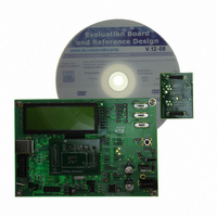
BOARD ST72651AR6/STTS75/STLM20
Manufacturer
STMicroelectronics
Specifications of STEVAL-IFS012V1
Sensor Type
Temperature
Sensing Range
Depends on IC
Interface
I²C, USB
Sensitivity
Depends on IC
Voltage - Supply
5V
Embedded
Yes, MCU, 8-Bit
Utilized Ic / Part
ST72F651AR6, STTS75, STLM20
Lead Free Status / RoHS Status
Lead free / RoHS Compliant
Other names
497-8419
Available stocks
Company
Part Number
Manufacturer
Quantity
Price


I²C SINGLE MASTER BUS INTERFACE (Cont’d)
I
Read Only
Reset Value: 0000 0000 (00h)
Bit 7 = EVF Event flag.
This bit is set by hardware as soon as an event oc-
curs. It is cleared by software reading SR2 register
in case of error event or as described in
It is also cleared by hardware when the interface is
disabled (PE=0).
0: No event
1: One of the following events has occurred:
Bit 6 = Reserved. Forced to 0 by hardware.
Bit 5 = TRA Transmitter/Receiver.
When BTF is set, TRA=1 if a data byte has been
transmitted. It is cleared automatically when BTF
is cleared. It is also cleared by hardware when the
interface is disabled (PE=0).
0: Data byte received (if BTF=1)
1: Data byte transmitted
Bit 4 = Reserved. Forced to 0 by hardware.
Bit 3 = BTF Byte transfer finished.
This bit is set by hardware as soon as a byte is cor-
rectly received or transmitted with interrupt gener-
ation if ITE=1. It is cleared by software reading
2
EVF
C STATUS REGISTER 1 (SR1)
– BTF=1 (Byte received or transmitted)
– SB=1 (Start condition generated)
– AF=1 (No acknowledge received after byte
– Address byte successfully transmitted.
7
transmission if ACK=1)
0
TRA
0
BTF
0
M/IDL
Figure
Doc ID 7215 Rev 4
SB
0
64.
SR1 register followed by a read or write of DR reg-
ister. It is also cleared by hardware when the inter-
face is disabled (PE=0).
– Following a byte transmission, this bit is set after
– Following a byte reception, this bit is set after
The SCL line is held low while BTF=1.
0: Byte transfer not done
1: Byte transfer succeeded
Bit 2 = Reserved. Forced to 0 by hardware.
Bit 1 = M/IDL Master/Idle.
This bit is set by hardware as soon as the interface
is in Master mode (writing START=1). It is cleared
by hardware after generating a Stop condition on
the bus. It is also cleared when the interface is dis-
abled (PE=0).
0: Idle mode
1: Master mode
Bit 0 = SB Start bit generated.
This bit is set by hardware as soon as the Start
condition
START=1). An interrupt is generated if ITE=1. It is
cleared by software reading SR1 register followed
by writing the address byte in DR register. It is also
cleared by hardware when the interface is disa-
bled (PE=0).
0: No Start condition
1: Start condition generated
reception of the acknowledge clock pulse. In
case an address byte is sent, this bit is set only
after the EV2 event (See
cleared by reading SR1 register followed by writ-
ing the next byte in DR register.
transmission of the acknowledge clock pulse if
ACK=1. BTF is cleared by reading SR1 register
followed by reading the byte from DR register.
is
generated
Figure
(following
64). BTF is
ST72651AR6
a
111/161
write
Related parts for STEVAL-IFS012V1
Image
Part Number
Description
Manufacturer
Datasheet
Request
R

Part Number:
Description:
BOARD EVAL SPZB260 MOD FOR STR9
Manufacturer:
STMicroelectronics
Datasheet:

Part Number:
Description:
BOARD EVAL EXTENSION SN250
Manufacturer:
STMicroelectronics
Datasheet:

Part Number:
Description:
BOARD EVAL AB-54003L-512
Manufacturer:
STMicroelectronics
Datasheet:

Part Number:
Description:
BOARD REF DESIGN RF DMOS PWR AMP
Manufacturer:
STMicroelectronics
Datasheet:

Part Number:
Description:
BOARD EVAL PWR AMP AB-84008L-470
Manufacturer:
STMicroelectronics
Datasheet:

Part Number:
Description:
BOARD EVAL FOR STM32F103XX
Manufacturer:
STMicroelectronics
Datasheet:

Part Number:
Description:
BOARD EVAL AB-54003L-512
Manufacturer:
STMicroelectronics
Datasheet:

Part Number:
Description:
BOARD SMART PLUG STM32 SPZB260PR
Manufacturer:
STMicroelectronics
Datasheet:

Part Number:
Description:
BOARD DEMO BLUETOOTH SPBT2532C2
Manufacturer:
STMicroelectronics
Datasheet:
Part Number:
Description:
ZIGBEE USB DONGLE EVAL KIT
Manufacturer:
STMicroelectronics
Datasheet:
Part Number:
Description:
STMicroelectronics [RIPPLE-CARRY BINARY COUNTER/DIVIDERS]
Manufacturer:
STMicroelectronics
Datasheet:
Part Number:
Description:
STMicroelectronics [LIQUID-CRYSTAL DISPLAY DRIVERS]
Manufacturer:
STMicroelectronics
Datasheet:

Part Number:
Description:
BOARD EVAL FOR MEMS SENSORS
Manufacturer:
STMicroelectronics
Datasheet: