STEVAL-IFS012V1 STMicroelectronics, STEVAL-IFS012V1 Datasheet - Page 69
STEVAL-IFS012V1
Manufacturer Part Number
STEVAL-IFS012V1
Description
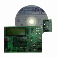
BOARD ST72651AR6/STTS75/STLM20
Manufacturer
STMicroelectronics
Specifications of STEVAL-IFS012V1
Sensor Type
Temperature
Sensing Range
Depends on IC
Interface
I²C, USB
Sensitivity
Depends on IC
Voltage - Supply
5V
Embedded
Yes, MCU, 8-Bit
Utilized Ic / Part
ST72F651AR6, STTS75, STLM20
Lead Free Status / RoHS Status
Lead free / RoHS Compliant
Other names
497-8419
Available stocks
Company
Part Number
Manufacturer
Quantity
Price


USB INTERFACE (Cont’d)
Bit 2 = PDWN Power down.
This bit is set by software to turn off the 3.3V on-
chip voltage regulator that supplies the external
pull-up resistor and the transceiver.
0: Voltage regulator on
1: Voltage regulator off
Note: After turning on the voltage regulator, soft-
ware should allow at least 3 μs for stabilisation of
the power supply before using the USB interface.
Bit 1 = FSUSP Force suspend mode.
This bit is set by software to enter Suspend mode.
The ST7 should also be put in Halt mode to reduce
power consumption.
0: Suspend mode inactive
1: Suspend mode active
When the hardware detects USB activity, it resets
this bit (it can also be reset by software).
Bit 0 = FRES Force reset.
This bit is set by software to force a reset of the
USB interface, just as if a RESET sequence came
from the USB.
0: Reset not forced
1: USB interface reset forced.
The USB interface is held in RESET state until
software clears this bit, at which point a “USB-RE-
SET” interrupt will be generated if enabled.
DEVICE ADDRESS REGISTER (DADDR)
Read/Write
Reset Value: 0000 0000 (00h)
Bit 7 Reserved, forced by hardware to 0.
Bits 6:0 = ADD[6:0] Device address, 7 bits.
Software must write into this register the address
sent by the host during enumeration.
7
0
ADD6 ADD5 ADD4 ADD3 ADD2 ADD1 ADD0
Doc ID 7215 Rev 4
0
Note: This register is also reset when a USB reset
is received or forced through bit FRES in the CTLR
register.
USB STATUS REGISTER (USBSR)
Read only
Reset Value: 0000 0000 (00h)
Bits 7:6 = PID[1:0] Token PID bits 1 & 0 for End-
point 0 Control.
USB token PIDs are encoded in four bits. PID[1:0]
correspond to the most significant bits of the PID
field of the last token PID received by Endpoint 0.
Note: The least significant PID bits have a fixed
value of 01.
When a CTR interrupt occurs on Endpoint 0 (see
register ISTR) the software should read the
PID[1:0] bits to retrieve the PID name of the token
received.
The USB specification defines PID bits as:
Bit 5 = IN/OUT Last transaction direction for End-
point 1 or 2.
This bit is set by hardware when a CTR interrupt
occurs on Endpoint 1 or Endpoint 2.
0: OUT transaction
1: IN transaction
Bits 4:3 = EP[1:0] Endpoint number.
These bits identify the endpoint which required at-
tention.
00 = Endpoint 0
01 = Endpoint 1
10 = Endpoint 2
PID1
7
PID1
0
1
1
PID0
OUT
IN/
PID0
EP1
0
0
1
EP0
ERR2 ERR1 ERR0
PID Name
ST72651AR6
SETUP
OUT
IN
69/161
0
1
Related parts for STEVAL-IFS012V1
Image
Part Number
Description
Manufacturer
Datasheet
Request
R

Part Number:
Description:
BOARD EVAL SPZB260 MOD FOR STR9
Manufacturer:
STMicroelectronics
Datasheet:

Part Number:
Description:
BOARD EVAL EXTENSION SN250
Manufacturer:
STMicroelectronics
Datasheet:

Part Number:
Description:
BOARD EVAL AB-54003L-512
Manufacturer:
STMicroelectronics
Datasheet:

Part Number:
Description:
BOARD REF DESIGN RF DMOS PWR AMP
Manufacturer:
STMicroelectronics
Datasheet:

Part Number:
Description:
BOARD EVAL PWR AMP AB-84008L-470
Manufacturer:
STMicroelectronics
Datasheet:

Part Number:
Description:
BOARD EVAL FOR STM32F103XX
Manufacturer:
STMicroelectronics
Datasheet:

Part Number:
Description:
BOARD EVAL AB-54003L-512
Manufacturer:
STMicroelectronics
Datasheet:

Part Number:
Description:
BOARD SMART PLUG STM32 SPZB260PR
Manufacturer:
STMicroelectronics
Datasheet:

Part Number:
Description:
BOARD DEMO BLUETOOTH SPBT2532C2
Manufacturer:
STMicroelectronics
Datasheet:
Part Number:
Description:
ZIGBEE USB DONGLE EVAL KIT
Manufacturer:
STMicroelectronics
Datasheet:
Part Number:
Description:
STMicroelectronics [RIPPLE-CARRY BINARY COUNTER/DIVIDERS]
Manufacturer:
STMicroelectronics
Datasheet:
Part Number:
Description:
STMicroelectronics [LIQUID-CRYSTAL DISPLAY DRIVERS]
Manufacturer:
STMicroelectronics
Datasheet:

Part Number:
Description:
BOARD EVAL FOR MEMS SENSORS
Manufacturer:
STMicroelectronics
Datasheet: