STEVAL-IFS012V1 STMicroelectronics, STEVAL-IFS012V1 Datasheet - Page 112
STEVAL-IFS012V1
Manufacturer Part Number
STEVAL-IFS012V1
Description
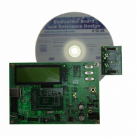
BOARD ST72651AR6/STTS75/STLM20
Manufacturer
STMicroelectronics
Specifications of STEVAL-IFS012V1
Sensor Type
Temperature
Sensing Range
Depends on IC
Interface
I²C, USB
Sensitivity
Depends on IC
Voltage - Supply
5V
Embedded
Yes, MCU, 8-Bit
Utilized Ic / Part
ST72F651AR6, STTS75, STLM20
Lead Free Status / RoHS Status
Lead free / RoHS Compliant
Other names
497-8419
Available stocks
Company
Part Number
Manufacturer
Quantity
Price


ST72651AR6
I²C SINGLE MASTER BUS INTERFACE (Cont’d)
I
Read Only
Reset Value: 0000 0000 (00h)
Bit 7:5 = Reserved. Forced to 0 by hardware.
Bit 4 = AF Acknowledge failure.
This bit is set by hardware when no acknowledge
is returned. An interrupt is generated if ITE=1. It is
cleared by software reading SR2 register or by
hardware when the interface is disabled (PE=0).
The SCL line is not held low while AF=1 but by oth-
er flags (SB or BTF) that are set at the same time.
0: No acknowledge failure
1: Acknowledge failure
Bit 3:0 = Reserved. Forced to 0 by hardware.
I
Read / Write
Reset Value: 0000 0000 (00h)
Bit 7 = FM/SM Fast/Standard I
This bit is set and cleared by software. It is not
cleared when the interface is disabled (PE=0).
0: Standard I
1: Fast I
Table 34. I
112/161
FM/SM
2
2
Address
C STATUS REGISTER 2 (SR2)
C CLOCK CONTROL REGISTER (CCR)
(Hex.)
7
0
7
40
41
42
CC6
2
0
C mode
2
CR
Reset Value
SR1
Reset Value
SR2
Reset Value
C Register Map
2
Register
CC5
C mode
Name
0
CC4
AF
CC3
EVF
0
7
0
0
0
2
C mode.
CC2
0
6
0
0
0
CC1
0
Doc ID 7215 Rev 4
CC0
0
0
0
TRA
PE
5
0
0
0
Bit 6:0 = CC6-CC0 7-bit clock divider.
These bits select the speed of the bus (F
pending on the I
when the interface is disabled (PE=0).
Refer to the Electrical Characteristics section for
the table of values.
Note: The programmed F
SCL and SDA lines.
I
Read / Write
Reset Value: 0000 0000 (00h)
Bit 7:0 = D7-D0 8-bit Data Register.
These bits contains the byte to be received or
transmitted on the bus.
– Transmitter mode: Byte transmission start auto-
– Receiver mode: the first data byte is received au-
2
C DATA REGISTER (DR)
matically when the software writes in the DR reg-
ister.
tomatically in the DR register using the least sig-
nificant bit of the address.
Then, the next data bytes are received one by
one after reading the DR register.
D7
7
AF
4
0
0
0
D6
START
BTF
3
0
0
0
D5
2
C mode. They are not cleared
D4
ACK
2
0
0
0
SCL
D3
assumes no load on
STOP
M/IDL
D2
1
0
0
0
D1
SCL
ITE
SB
0
0
0
0
) de-
D0
0
Related parts for STEVAL-IFS012V1
Image
Part Number
Description
Manufacturer
Datasheet
Request
R

Part Number:
Description:
BOARD EVAL SPZB260 MOD FOR STR9
Manufacturer:
STMicroelectronics
Datasheet:

Part Number:
Description:
BOARD EVAL EXTENSION SN250
Manufacturer:
STMicroelectronics
Datasheet:

Part Number:
Description:
BOARD EVAL AB-54003L-512
Manufacturer:
STMicroelectronics
Datasheet:

Part Number:
Description:
BOARD REF DESIGN RF DMOS PWR AMP
Manufacturer:
STMicroelectronics
Datasheet:

Part Number:
Description:
BOARD EVAL PWR AMP AB-84008L-470
Manufacturer:
STMicroelectronics
Datasheet:

Part Number:
Description:
BOARD EVAL FOR STM32F103XX
Manufacturer:
STMicroelectronics
Datasheet:

Part Number:
Description:
BOARD EVAL AB-54003L-512
Manufacturer:
STMicroelectronics
Datasheet:

Part Number:
Description:
BOARD SMART PLUG STM32 SPZB260PR
Manufacturer:
STMicroelectronics
Datasheet:

Part Number:
Description:
BOARD DEMO BLUETOOTH SPBT2532C2
Manufacturer:
STMicroelectronics
Datasheet:
Part Number:
Description:
ZIGBEE USB DONGLE EVAL KIT
Manufacturer:
STMicroelectronics
Datasheet:
Part Number:
Description:
STMicroelectronics [RIPPLE-CARRY BINARY COUNTER/DIVIDERS]
Manufacturer:
STMicroelectronics
Datasheet:
Part Number:
Description:
STMicroelectronics [LIQUID-CRYSTAL DISPLAY DRIVERS]
Manufacturer:
STMicroelectronics
Datasheet:

Part Number:
Description:
BOARD EVAL FOR MEMS SENSORS
Manufacturer:
STMicroelectronics
Datasheet: