MC56F8367EVME Freescale Semiconductor, MC56F8367EVME Datasheet - Page 130
MC56F8367EVME
Manufacturer Part Number
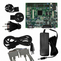
MC56F8367EVME
Description
EVAL BOARD FOR MC56F83X
Manufacturer
Freescale Semiconductor
Type
DSPr
Specifications of MC56F8367EVME
Contents
Module and Misc Hardware
Processor To Be Evaluated
MC56F8145-67 and MC56F8345-67
Data Bus Width
16 bit
Interface Type
RS-232
Silicon Manufacturer
Freescale
Core Architecture
56800/E
Core Sub-architecture
56800/E
Silicon Core Number
MC56F
Silicon Family Name
MC56F83xx
Rohs Compliant
Yes
For Use With/related Products
MC56F83x5, MC56F83x6, MC56F83x7
Lead Free Status / RoHS Status
Lead free / RoHS Compliant


of security. When Flash security mode is enabled in accordance with the method described in the Flash
Memory module specification, the device will disable external P-space accesses restricting code execution
to internal memory, disable EXTBOOT=1 mode, and disable the core EOnCE debug capabilities. Normal
program execution is otherwise unaffected.
7.2 Flash Access Blocking Mechanisms
The 56F8367/56F8167 have several operating functional and test modes. Effective Flash security must
address operating mode selection and anticipate modes in which the on-chip Flash can be compromised
and read without explicit user permission. Methods to block these are outlined in the next subsections.
7.2.1
At boot time, the SIM determines in which functional modes the device will operate. These are:
When Flash security is enabled as described in the Flash Memory module specification, the device will
boot in internal boot mode, disable all access to external P-space, and start executing code from the Boot
Flash at address 0x02_0000.
This security affords protection only to applications in which the device operates in internal Flash security
mode. Therefore, the security feature cannot be used unless all executing code resides on-chip.
When security is enabled, any attempt to override the default internal operating mode by asserting the
EXTBOOT pin in conjunction with reset will be ignored.
7.2.2
On-chip Flash can be read by issuing commands across the EOnCE port, which is the debug interface for
the 56800E core. The TRST, TCLK, TMS, TDO, and TDI pins comprise a JTAG interface onto which the
EOnCE port functionality is mapped. When the device boots, the chip-level JTAG TAP (Test Access Port)
is active and provides the chip’s boundary scan capability and access to the ID register.
Proper implementation of Flash security requires that no access to the EOnCE port is provided when
security is enabled. The 56800E core has an input which disables reading of internal memory via the
JTAG/EOnCE. The FM sets this input at reset to a value determined by the contents of the FM security
bytes.
7.2.3
If a user inadvertently enables Flash security on the device, a built-in lockout recovery mechanism can be
used to reenable access to the device. This mechanism completely reases all on-chip Flash, thus disabling
Flash security. Access to this recovery mechanism is built into CodeWarrior via an instruction in memory
configuration (.cfg) files. Add, or uncomment the following configuration command:
unlock_flash_on_connect 1
For more information, please see CodeWarrior MC56F83xx/DSP5685x Family Targeting Manual.
130
•
•
•
Internal Boot Mode
External Boot Mode
Secure Mode
Forced Operating Mode Selection
Disabling EOnCE Access
Flash Lockout Recovery
56F8367 Technical Data, Rev. 8
Freescale Semiconductor
Preliminary
Related parts for MC56F8367EVME
Image
Part Number
Description
Manufacturer
Datasheet
Request
R

Part Number:
Description:
56f8300 16-bit Digital Signal Controllers
Manufacturer:
Freescale Semiconductor, Inc
Datasheet:
Part Number:
Description:
Manufacturer:
Freescale Semiconductor, Inc
Datasheet:
Part Number:
Description:
Manufacturer:
Freescale Semiconductor, Inc
Datasheet:
Part Number:
Description:
Manufacturer:
Freescale Semiconductor, Inc
Datasheet:
Part Number:
Description:
Manufacturer:
Freescale Semiconductor, Inc
Datasheet:
Part Number:
Description:
Manufacturer:
Freescale Semiconductor, Inc
Datasheet:
Part Number:
Description:
Manufacturer:
Freescale Semiconductor, Inc
Datasheet:
Part Number:
Description:
Manufacturer:
Freescale Semiconductor, Inc
Datasheet:
Part Number:
Description:
Manufacturer:
Freescale Semiconductor, Inc
Datasheet:
Part Number:
Description:
Manufacturer:
Freescale Semiconductor, Inc
Datasheet:
Part Number:
Description:
Manufacturer:
Freescale Semiconductor, Inc
Datasheet:
Part Number:
Description:
Manufacturer:
Freescale Semiconductor, Inc
Datasheet:
Part Number:
Description:
Manufacturer:
Freescale Semiconductor, Inc
Datasheet:
Part Number:
Description:
Manufacturer:
Freescale Semiconductor, Inc
Datasheet:
Part Number:
Description:
Manufacturer:
Freescale Semiconductor, Inc
Datasheet: