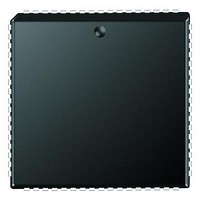
PIC18F6680-I/L Microchip Technology, PIC18F6680-I/L Datasheet - Page 344

PIC18F6680-I/L
Manufacturer Part Number
PIC18F6680-I/L
Description
Microcontrollers (MCU) 64KB 3328 RAM 52 I/O
Manufacturer
Microchip Technology
Datasheet
1.PCM18XK1.pdf
(496 pages)
Specifications of PIC18F6680-I/L
Processor Series
PIC18F
Core
PIC
Data Bus Width
8 bit
Data Ram Size
3.25 KB
Interface Type
I2C/SPI/AUSART/CAN
Maximum Clock Frequency
40 MHz
Number Of Programmable I/os
53
Number Of Timers
5
Operating Supply Voltage
4.2 V to 5.5 V
Maximum Operating Temperature
+ 85 C
Mounting Style
SMD/SMT
3rd Party Development Tools
52715-96, 52716-328, 52717-734, 52712-325, EWPIC18
Development Tools By Supplier
PG164130, DV164035, DV244005, DV164005, PG164120, ICE2000, ICE4000, DV164136
Minimum Operating Temperature
- 40 C
On-chip Adc
12-ch x 10-bit
Program Memory Type
Flash
Program Memory Size
64 KB
Package / Case
PLCC-68
Lead Free Status / RoHS Status
Lead free / RoHS Compliant
Available stocks
Company
Part Number
Manufacturer
Quantity
Price
Company:
Part Number:
PIC18F6680-I/L
Manufacturer:
RUBYCON
Quantity:
46 000
Part Number:
PIC18F6680-I/L
Manufacturer:
MICROCH
Quantity:
20 000
- Current page: 344 of 496
- Download datasheet (9Mb)
PIC18F6585/8585/6680/8680
FIGURE 23-7:
23.15 CAN Interrupts
The module has several sources of interrupts. Each of
these interrupts can be individually enabled or dis-
abled. The PIR3 register contains interrupt flags. The
PIE3 register contains the enables for the 8 main inter-
rupts. A special set of read-only bits in the CANSTAT
register, the ICODE bits, can be used in combination
with a jump table for efficient handling of interrupts.
All interrupts have one source with the exception of the
error interrupt and buffer interrupts in Mode 1 and 2. Any
of the error interrupt sources can set the error interrupt
flag. The source of the error interrupt can be determined
by
COMSTAT. In Mode 1 and 2, there are two interrupt
enable/disable and flag bits – one for all transmit buffers
and the other for all receive buffers.
The interrupts can be broken up into two categories:
receive and transmit interrupts.
The receive related interrupts are:
• Receive Interrupts
• Wake-up Interrupt
• Receiver Overrun Interrupt
• Receiver Warning Interrupt
• Receiver Error-Passive Interrupt
DS30491C-page 342
reading
the
Communication
ERROR MODES STATE DIAGRAM
RXERRCNT < 127 or
TXERRCNT < 127
Passive
Error
Status
-
register,
TXERRCNT > 255
RXERRCNT > 127 or
TXERRCNT > 127
Active
Error
priority interrupt that is pending (if any) will be reflected
The transmit related interrupts are:
• Transmit Interrupts
• Transmitter Warning Interrupt
• Transmitter Error-Passive Interrupt
• Bus-Off Interrupt
23.15.1
To simplify the interrupt handling process in user firm-
ware, the ECAN module encodes a special set of bits. In
Mode 0, these bits are ICODE<2:0> in the CANSTAT
register. In Mode 1 and 2, these bits are EICODE<3:0>
in the CANSTAT register. Interrupts are internally priori-
tized such that the higher priority interrupts are assigned
lower values. Once the highest priority interrupt condi-
tion has been cleared, the code for the next highest
by the ICODE bits. Note that only those interrupt sources
that have their associated interrupt enable bit set will be
reflected in the ICODE bits.
In Mode 2, when a receive message interrupt occurs,
EICODE bits will always consist of ‘10000’. User
firmware may use FIFO pointer bits to actually access
the next available buffer.
-
Bus
Off
-
INTERRUPT CODE BITS
Reset
128 occurrences of
11 consecutive
“recessive” bits
2004 Microchip Technology Inc.
Related parts for PIC18F6680-I/L
Image
Part Number
Description
Manufacturer
Datasheet
Request
R

Part Number:
Description:
20-Pin USB Flash Microcontrollers
Manufacturer:
MICROCHIP [Microchip Technology]
Datasheet:

Part Number:
Description:
PIC18F With 128-segment LCD Driver And 12-bit ADC, 8KB Flash, 768B RAM, CCP, MSS
Manufacturer:
Microchip Technology
Datasheet:

Part Number:
Description:
PIC18F With 128-segment LCD Driver And 12-bit ADC, 16KB Flash, 768B RAM, CCP, MS
Manufacturer:
Microchip Technology
Datasheet:

Part Number:
Description:
PIC18F With 192-segment LCD Driver And 12-bit ADC, 8KB Flash, 768B RAM, CCP, MSS
Manufacturer:
Microchip Technology
Datasheet:

Part Number:
Description:
PIC18F With 192-segment LCD Driver And 12-bit ADC, 16KB Flash, 768B RAM, CCP, MS
Manufacturer:
Microchip Technology
Datasheet:

Part Number:
Description:
Microcontrollers (MCU) 48KB 3328 RAM 52 I/O
Manufacturer:
Microchip Technology
Datasheet:

Part Number:
Description:
32kB Flash, 2kB RAM, 1kB EE, NanoWatt XLP, LCD 64 QFN 9x9x0.9mm T/R
Manufacturer:
Microchip Technology
Datasheet:

Part Number:
Description:
32kB Flash, 2kB RAM, 1kB EE, NanoWatt XLP, LCD 64 TQFP 10x10x1mm T/R
Manufacturer:
Microchip Technology
Datasheet:

Part Number:
Description:
128kB Flash, 4kB RAM, 1kB EE, 16MIPS, NanoWatt XLP, LCD, 5V 80 TQFP 12x12x1mm T/
Manufacturer:
Microchip Technology
Datasheet:

Part Number:
Description:
32kB Flash, 2kB RAM, 1kB EE, NanoWatt XLP, LCD 64 QFN 9x9x0.9mm TUBE
Manufacturer:
Microchip Technology
Datasheet:

Part Number:
Description:
32kB Flash, 2kB RAM, 1kB EE, NanoWatt XLP, LCD 64 TQFP 10x10x1mm TRAY
Manufacturer:
Microchip Technology

Part Number:
Description:
128kB Flash, 4kB RAM, 1kB EE, 16MIPS, NanoWatt XLP, LCD, 5V 80 TQFP 12x12x1mm TR
Manufacturer:
Microchip Technology

Part Number:
Description:
Manufacturer:
Microchip Technology Inc.
Datasheet:


